4
Safety device to safeguard against overheating of
the underfloor heating system, in accordance with
prevailing regulations
Reversing valve
Flow temperature sensor
Lead boiler
Secondary boiler
Connection diagram: Boilers in cascade + 1 direct circuit + 1 un
derfloor heating circuit + 1 domestic hot water tank, page 35.
Configuring boilers in cascade + 1 direct circuit + 1 underfloor
heating circuit + 1 domestic hot water tank, page 65.
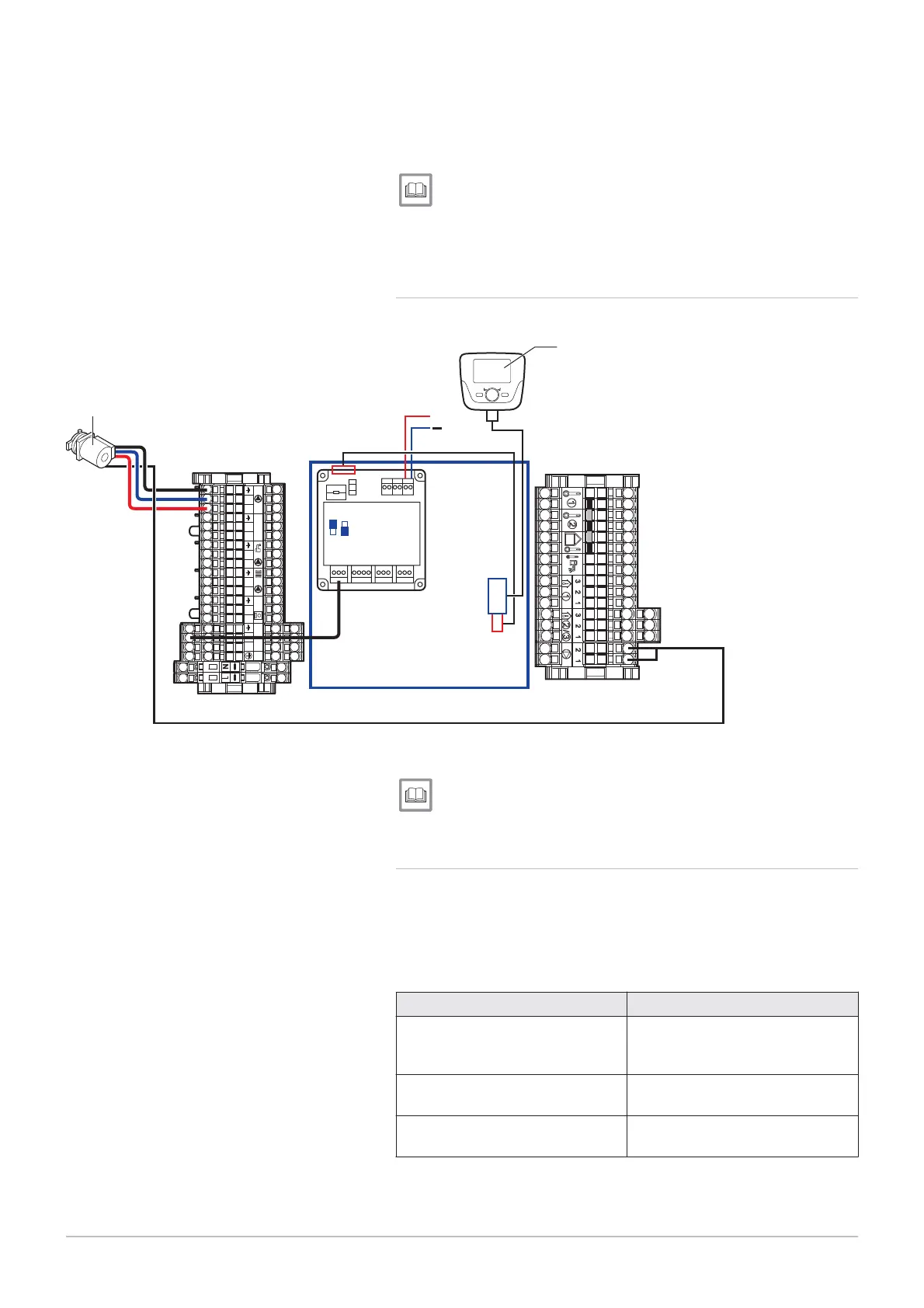
6.6.10 Electrical connection: controlling a boiler in 0/10V
Fig.62 Controlling a boiler in 0/10V
1
2
3
4
Aux 1-2 230 V
TA TS
LN LN L LNNLNLN
MW-3000041-01
34
AVS75
38
+
Primary pump 3
Remote control with or without room temperature
sensor
Connection diagram: controlling a boiler in 0/10 V, page 36.
Configuring control of a boiler in 0/10V, page 65.
6.6.11 Connecting boilers in cascade with an OCI 345 interface
Connect the boilers making up the boiler cascade with O
interfaces,
electronic devices that handle communication through a B
link. The
interfaces must be connected to each boiler with three connec
tors.
Tab.19 Connecting the components of the boiler cascade
Component 1 Component 2
OCI 345
unit on the boiler X
connector on the boiler's PCB
(flat cable supplied with the O
accessory)
connector for an O
unit
on a boiler
connector for an O
unit
on a boiler
connector for an O
unit
on a boiler
connector for an O
unit
on a boiler
6 Installation
54 7609474 - v02 - 04092014
 Loading...


