EasyManua.ls Logo

Brother PT-1900 User Manual

Brother PT-1900
101 pages
To Next Page IconTo Next Page
To Previous Page IconTo Previous Page
Page #2 background imageLoading...
Page #2 background image
PREFACE
This publication is a service manual covering the specifications, general mechanisms,
disassembly/reassembly procedure, and troubleshooting and error message of the Brother PT-
1900/1910/1850. It is intended for service personnel and other concerned persons to accurately
and quickly provide after-sale service for our PT-1900/1910/1850.
To perform appropriate maintenance so that the machine is always in best condition for the
customer, the service personnel must adequately understand and apply this manual.
This manual is made up of four chapters and appendices.
CHAPTER I SPECIFICATIONS
CHAPTER II GENERAL MECHANISMS
CHAPTER III DISASSEMBLY & REASSEMBLY PROCEDURE
CHAPTER IV TROUBLESHOOTING AND ERROR MESSAGE
APPENDIX 1. CIRCUIT DIAGRAMS
© Copyright Brother 2002
All rights reserved.
No part of this publication may be reproduced in any
form or by any means without permission in writing
from the publisher.
Specifications are subject to change without notice.

Table of Contents

Question and Answer IconNeed help?

Do you have a question about the Brother PT-1900 and is the answer not in the manual?
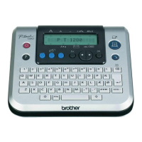
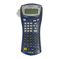
Brother PT-1900 Specifications

General IconGeneral
ModelPT-1900
Device CategoryLabel Maker
DisplayLCD
Print TechnologyThermal Transfer
Maximum Print Resolution180 dpi
KeyboardQWERTY
Maximum Print Width12 mm
Print Speed10 mm / sec
Tape Width6 mm, 9 mm, 12 mm
Power Source6 AA batteries or AC adapter

Summary

Preface

CHAPTER III DISASSEMBLY & REASSEMBLY

3.1 DISASSEMBLY PROCEDURE

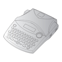
Detailed steps for disassembling the Brother PT-1900/1910/1850, covering component removal.

3.2 REASSEMBLY PROCEDURE

Step-by-step instructions for reassembling the Brother PT-1900/1910/1850 after service.

CHAPTER IV TROUBLESHOOTING AND ERROR MESSAGE

4.1 TROUBLESHOOTING

Procedures and flows for diagnosing and resolving common issues encountered with the Brother PT-1900/1910/1850.

4.2 ERROR MESSAGE

List of error messages displayed by the Brother PT-1900/1910/1850 and their meanings.

Appendix 1. CIRCUIT DIAGRAMS

CHAPTER I SPECIFICATIONS

1.1 MECHANICAL SPECIFICATIONS

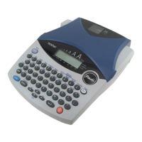
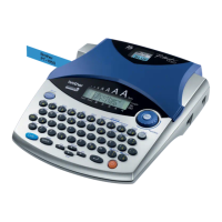
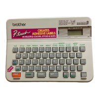
Details on the physical dimensions, weight, and external features of the Brother PT-1900/1910/1850.

1.2 ELECTRONICS SPECIFICATIONS

Technical specifications related to the character generator, power supply, and internal memory of the device.

1.3 KEY COMMANDS FOR SPECIAL FUNCTIONS

Instructions on using specific key combinations for initialization and demonstration print functions.

1.1.1 External Appearance

1.1.2 Keyboard

1.1.3 Display

1.1.4 Printing Mechanism

1.1.5 Tape Cassette

1.1.6 Tape Cutter

1.2.1 Character Generator

1.2.2 Power Supply

1.3.1 Initializing

1.3.2 Demonstration Print

CHAPTER II GENERAL MECHANISMS

2.1 MAIN MECHANISM

Explanation of the primary mechanical systems within the Brother PT-1900/1910/1850, including print and feed.

2.2 OUTLINE OF CONTROL ELECTRONICS

Overview of the electronic components and their configuration in the Brother PT-1900/1910/1850.

2.1.1 Print Mechanism

2.1.2 Roller Holder ASSY Setting & Retracting Mechanism

2.1.3 Tape & Ribbon Feed Mechanism

2.1.4 Automatic Tape Cutter Mechanism (PT-1900/1910)

2.1.5 Tape Cutter Mechanism (PT-1850)

2.1.6 Roller Holder ASSY & Cassette Cover Interlocking Mechanism

2.2.1 Configuration of the Electronic Part

2.2.2 Main PCB

2.2.3 Power Supply PCB

2.2.4 Cassette Sensor

2.2.5 DC Motors

2.2.6 Thermal Print Head

2.3 MAIN PCB

2.3.1 Block Diagram

Block diagram illustrating the components and connections of the main PCB in the Brother PT-1900/1910/1850.

2.3.2 Solder Points

2.4 POWER SUPPLY PCB

Appendix 1.C Sub PCB Circuit Diagram

Related product manuals