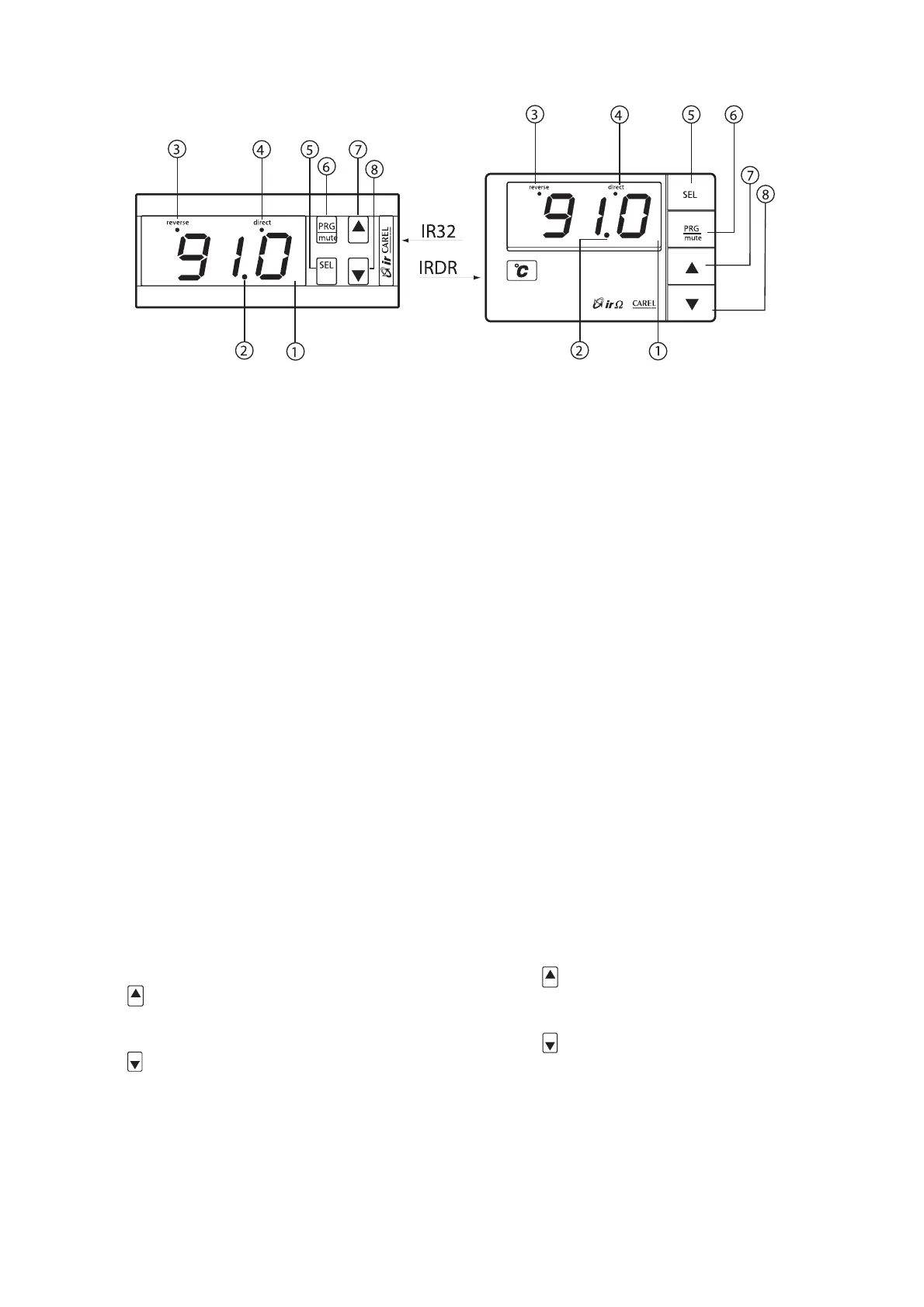
1.2 Descrizione del frontale degli strumenti
1 – Display: visualizza il valore della sonda collegata.
In caso di allarme il valore della sonda viene visualizzato alterna-
tivamente ai codici degli allarmi attivi. Durante la programmazio-
ne mostra i codici dei parametri ed il loro valore.
2 – LED decimale: viene acceso quando la grandezza controllata
è visualizzata con la risoluzione del decimo.
3 – LED Reverse: lampeggia quando almeno un relè con funzio-
namento “Reverse” è attivo. Il numero di lampeggi indica i relè
attivi in Reverse. Tra una fase di lampeggio
e la successiva il LED rimane spento per 2 secondi.
4 – LED Direct: lampeggia quando è attivo almeno un relè in
funzionamento “Direct”. Valgono le altre considerazioni viste per
la funzione “Reverse”.
5 – Tasto SEL: visualizza e/o imposta il set point. Se premuto
insieme al tasto PRG/MUTE per 5 secondi permette di inserire la
password e di accedere ai parametri di configurazione (parametri
con codice tipo “Cxx”).
6 – Tasto PRG/Mute: premuto per 5 secondi dà accesso al menù
dei parametri di utilizzo più frequente (codice tipo “Pxx”). In caso
di allarme tacita il buzzer. Resetta le altre segnalazioni d’allarme
se premuto al cessare della causa.
Termina la programmazione fissando in memoria i valori dei
parametri modificati.
7 – Tasto
: incrementa il valore del set-point o di ogni altro
parametro selezionato.
8 – Tasto
: decrementa il valore del set-point o di ogni altro
parametro selezionato. Nelle versioni con ingresso NTC, se
premuto quando sul display è visualizzato il valore della sonda
principale, permette la visualizzazione della seconda sonda per il
tempo in cui il tasto resta premuto.
Nota: per i codici dei modelli della serie Infrared Universale, fare
riferimento alla tabella alla fine del manuale.
1.2 Front panel
1 – Display: shows the value measured by the connected sen-
sor. In the event of alarm condition the sensor value will be
displayed alternately with the codes of the active alarms. When
programming the instrument, the display shows the parameter
codes being introduced and their values.
2 – Decimal Point LED: lights up when the controlled parameter
is displayed.
3 – Reverse LED: flashes when at least one relay working in the
“Reverse” mode is active. The Led flashes as many times as the
number of active ‘reverse’ relays. There is a two seconds’ pause
between a flashing stage and the next one.
4 – Direct LED: flashes when at least one relay working in the
“Direct” mode is active. Its working logic is the same as the
“Reverse” LED.
5 – SEL Button: displays and/or allows you to select the Set-
point. If pressed for 5 seconds together with PRG/MUTE it allows
you to enter the password and the configuration parameters
(having a “Cxx” type code).
6 – PRG/Mute Button: if pressed for 5 seconds it allows you
to access the menu of the more frequently used parameters
(having a “Pxx” type code). In the event of alarm condition, it
silences the buzzer and, if pressed after the cause that determi-
ned the alarm has disappeared, it resets any other alarm. It com-
pletes the programming procedure storing all the values of the
modified parameters.
7 – Button
: increases the value of the set-point or that of
any other selected parameter.
8 – Button
: decreases the value of the set-point or that of
any other selected parameter. In NTC input versions it can
display the value of the second sensor (holding “Down” pressed
while the display shows the value of the main sensor).
Nota: per i codici dei modelli della serie Infrared Universale, fare
riferimento alla tabella alla fine del manuale.
2
Fig.1

 Loading...