Standard Chiller/HP modulare per compressore a vite con driver CAREL
Cod.: +030221241 Rel. 1.0 dated 25 September 03
8
6 LIST OF INPUTS/OUTPUTS
Inputs and outputs are listed below based on unit type. A number has been associated with each type of machine. This number is the program's
main parameter because it identifies the inputs and outputs configuration. Using this list of inputs and outputs, select the number you require
from the numbers associated in the program configuration screens.
AIR/WATER UNIT WITH MAX. 4 SCREW COMPRESSORS (UP TO 4 CAPACITY STAGES PER COMPRESSOR)
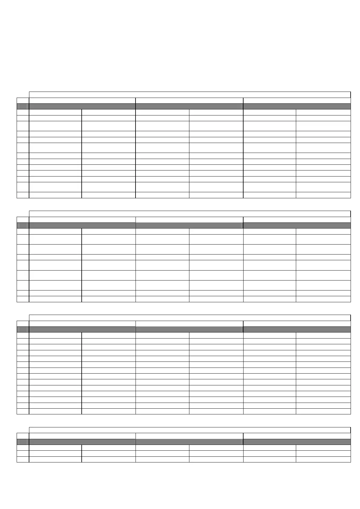
6.1 CHILLER-ONLY UNIT - MACHINE TYPE “0”
6.1.1 DIGITAL INPUTS
Chiller-only unit MACHINE TYPE “0”
N. pCO2 MEDIUM pCO1 MEDIUM pCOC MEDIUM
Master (Address 1) Slave (addresses 2/3/4) Master (Address 1) Slave (addresses 2/3/4) Master (Address 1) Slave (addresses 2/3/4)
1
Serious alarm (enablable) Serious alarm (enablable) Serious alarm (enablable) Serious alarm (enablable) Serious alarm (enablable) Serious alarm (enablable)
2
Evaporator Flow-switch
(enablable)
Evaporator Flow-switch
(enablable)
Evaporator Flow-switch
(enablable)
Evaporator Flow-switch
(enablable)
Evaporator Flow-switch
(enablable)
Evaporator Flow-switch
(enablable)
3
Remote ON/OFF Remote ON/OFF Remote ON/OFF Remote ON/OFF Remote ON/OFF Remote ON/OFF
4
Pump Thermal cutout Pump Thermal cutout Pump Thermal cutout
5
Low Pressure 2 Pressure-
switch
Low Pressure 2 Pressure-
switch
Low Pressure 2 Pressure-
switch
Low Pressure 2 Pressure-
switch
Low Pressure 2 Pressure-
switch
Low Pressure 2 Pressure-
switch
6
Differential / Oil Level Differential / Oil Level Differential / Oil Level Differential / Oil Level Differential / Oil Level Differential / Oil Level
7
Phase Monitor (enablable) Phase Monitor (enablable) Phase Monitor (enablable) Phase Monitor (enablable) Phase Monitor (enablable) Phase Monitor (enablable)
8
Double Set-point Double Set-point Double Set-point
9
Fan 1 Thermal cutout Fan 1 Thermal cutout Fan 1 Thermal cutout Fan 1 Thermal cutout Fan 1 Thermal cutout Fan 1 Thermal cutout
10
Fan 2 Thermal cutout Fan 2 Thermal cutout Fan 2 Thermal cutout Fan 2 Thermal cutout Fan 2 Thermal cutout Fan 2 Thermal cutout
11
High Pressure Pressure-
switch
High Pressure Pressure-
switch
High Pressure Pressure-
switch
High Pressure Pressure-
switch
High Pressure Pressure-
switch
High Pressure Pressure-
switch
12
Compressor Thermal cutout Compressor Thermal cutout Compressor Thermal cutout Compressor Thermal cutout Compressor Thermal cutout Compressor Thermal cutout
6.1.2 ANALOGUE INPUTS
Chiller-only unit MACHINE TYPE “0”
N. pCO2 MEDIUM pCO1 MEDIUM pCOC MEDIUM
Master (Address 1) Slave (addresses 2/3/4) Master (Address 1) Slave (addresses 2/3/4) Master (Address 1) Slave (addresses 2/3/4)
1
Water temperature at
Evaporator Inlet
High Pressure High Pressure Water temperature at
Evaporator Inlet
2
Water temperature at
Evaporator Outlet
Water temperature at
Evaporator Outlet
Low Pressure Low Pressure Water temperature at
Evaporator Outlet
Water temperature at
Evaporator Outlet
3
Delivery Temperature Delivery Temperature Delivery Temperature Delivery Temperature Condenser Temperature Condenser Temperature
4
Voltage / Current / External
Set-point
Voltage / Current
5
Condenser Temperature Condenser Temperature Water temperature at
Evaporator Inlet
Voltage / Current / External
Set-point
Voltage / Current
6
Voltage / Current / External
Set-point
Voltage / Current Water temperature at
Evaporator Outlet
Water temperature at
Evaporator Outlet
Delivery Temperature Delivery Temperature
7
High Pressure High Pressure Condenser Temperature Condenser Temperature High Pressure High Pressure
8
Low Pressure Low Pressure Low Pressure Low Pressure
6.1.3 DIGITAL OUTPUTS
Chiller-only unit MACHINE TYPE “0”
N. pCO2 MEDIUM pCO1 MEDIUM pCOC MEDIUM
Master (Address 1) Slave (addresses 2/3/4) Master (Address 1) Slave (addresses 2/3/4) Master (Address 1) Slave (addresses 2/3/4)
1
Circulation Pump Circulation Pump Circulation Pump
2
Line Contactor Line Contactor Line Contactor Line Contactor Line Contactor Line Contactor
3
Star Contactor Star Contactor Star Contactor Star Contactor Star Contactor Star Contactor
4
Triangle Contactor Triangle Contactor Triangle Contactor Triangle Contactor Triangle Contactor Triangle Contactor
5
Liquid Solenoid Liquid Solenoid Liquid Solenoid Liquid Solenoid Liquid Solenoid Liquid Solenoid
6
Capacity Control Relay 1 Capacity Control Relay 1 Capacity Control Relay 1 Capacity Control Relay 1 Capacity Control Relay 1 Capacity Control Relay 1
7
Capacity Control Relay 2 Capacity Control Relay 2 Capacity Control Relay 2 Capacity Control Relay 2 Capacity Control Relay 2 Capacity Control Relay 2
8
Capacity Control Relay 3 Capacity Control Relay 3 Capacity Control Relay 3 Capacity Control Relay 3 Capacity Control Relay 3 Capacity Control Relay 3
9
Liquid inj./Econ/Oil Cooler Liquid inj./Econ/Oil Cooler Liquid inj./Econ/Oil Cooler Liquid inj./Econ/Oil Cooler Liquid inj./Econ/Oil Cooler Liquid inj./Econ/Oil Cooler
10
Antifreeze Heater Antifreeze Heater Antifreeze heater C 1 Antifreeze Heater Antifreeze Heater Antifreeze Heater
11
General Alarm General Alarm General Alarm General Alarm General Alarm General Alarm
12
Fan 1 Fan 1 Fan 1 Fan 1 Fan 1 Fan 1
13
Fan 2 Fan 2 Fan 2 Fan 2 Fan 2 Fan 2
6.1.4 ANALOGUE OUTPUTS
Chiller-only unit MACHINE TYPE “0”
N. pCO2 MEDIUM pCO1 MEDIUM pCOC MEDIUM
Master (Address 1) Slave (addresses 2/3/4) Master (Address 1) Slave (addresses 2/3/4) Master (Address 1) Slave (addresses 2/3/4)
1
Speed Controller Speed Controller Speed Controller Speed Controller Speed Controller Speed Controller
2

 Loading...


