Standard Chiller/HP modulare per compressore a vite con driver CAREL
Cod.: +030221241 Rel. 1.0 dated 25 September 03
49
22 Supervisor
The unit can be interfaced to a local or remote supervision/remote-assistance system.
pCO card accessories include an optional card for serial communication through interface RS422 or RS485, supplied separately from the pCO
card.
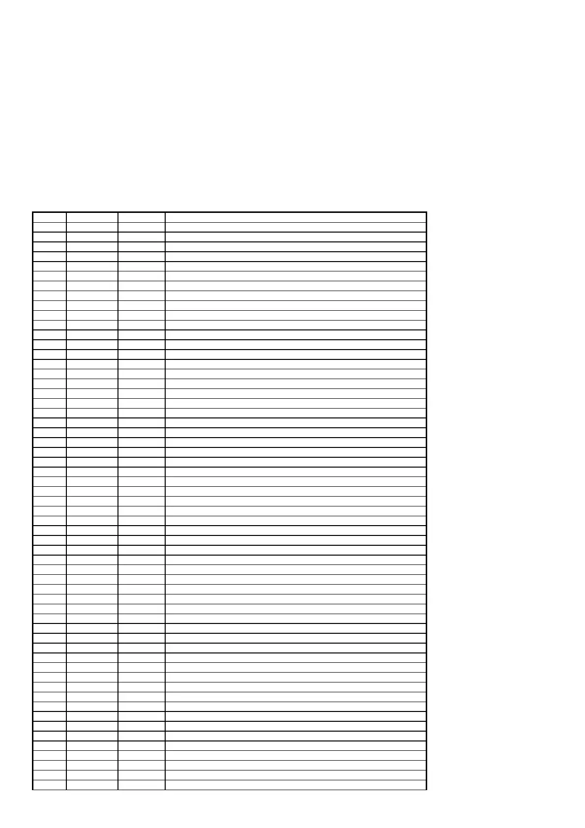
If the serial communication values (serial address and communication speed) are correctly set, the parameters transmitted by the unit will be as
shown on the following table.
22.1.1 Key
A Analogue variables
D Digital variables
I Entire variable
IN Input variables pCO
Supervisor
OUT Output variable pCO
% Supervisor
IN/OUT Input/output variable pCO
Supervisor
Type Direction Address Description
A OUT 1 Analogue input 1 value
A OUT 2 Analogue input 2 value
A OUT 3 Analogue input 3 value
A OUT 4 Analogue input 4 value
A OUT 5 Analogue input 5 value
A OUT 6 Analogue input 6 value
A OUT 7 Analogue input 7 value
A OUT 8 Analogue input 8 value
A OUT 9 Analogue output 1 value
A OUT 10 Analogue output 2 value
A IN/OUT 11 Summer temperature set-point
A IN/OUT 12 Winter temperature set-point
A IN/OUT 13 Condensation set-point
A IN/OUT 14 Temperature control band
I OUT 1 Status of unit
I OUT 2 pLAN address of unit
I IN/OUT 3 Type of fan management
I IN/OUT 4 Unit configuration type
I IN/OUT 5 Number of compressors
I IN/OUT 6 Number of fans
D OUT 1 Status of unit
D OUT 2 Digital output 1 value
D OUT 3 Digital output 2 value
D OUT 4 Digital output 3 value
D OUT 5 Digital output 4 value
D OUT 6 Digital output 5 value
D OUT 7 Digital output 6 value
D OUT 8 Digital output 7 value
D OUT 9 Digital output 8 value
D OUT 10 Digital output 9 value
D OUT 11 Digital output 10 value
D OUT 12 Digital output 11 value
D OUT 13 Digital output 12 value
D OUT 14 Digital output 13 value
D OUT 15 Enable evaporator flow-switch alarm
D OUT 16 Enable probe 1
D OUT 17 Enable probe 2
D OUT 18 Enable probe 3
D OUT 19 Enable probe 4
D OUT 20 Enable probe 5
D OUT 21 Enable probe 6
D OUT 22 Enable probe 7
D IN/OUT 23 Enable probe 8
D IN/OUT 24 ON/OFF from Supervisor
D IN/OUT 25 Enable starting restrictions
D IN/OUT 26 Type of compressor capacity control
D OUT 27 Summer/Winter selection from digital input
D OUT 28
D OUT 29 Summer/Winter operation
D OUT 30 Selection of condensation with inverter
D OUT 45
D OUT 46 Antifreeze alarm
D OUT 47 Compressor thermal overload alarm
D OUT 48 Evaporator flow-switch alarm
D OUT 49 Condenser flow-switch alarm
D OUT 50 High pressure alarm from pressure switch

 Loading...


