Standard Chiller/HP modulare per compressore a vite con driver CAREL
Cod.: +030221241 Rel. 1.0 dated 25 September 03
28
11.5 Continuous capacity control with control at outlet
Temperature control with compressors on continuous capacity control can occur only if control at outlet is selected, according to the
temperature values measured by the probe located at evaporator outlet.
To that end, further configuration parameters are input. They are specific for the particular type of compressor, and are added to those
previously mentioned in the description of the special type of control.
Parameters used
:
• Neutral zone for continuous capacity control
• Impulse period
• Charging impulse minimum duration
• Charging impulse maximum duration
• Discharging impulse minimum duration
• Discharging impulse maximum duration
• Forced discharge period at compressor power-up
• Capacity control relay forcing enabled when compressor is OFF:
Outputs used :
• Compressor capacity control Relay 1
• Compressor capacity control Relay 2
B
Control set point
A
Forced power-down
threshold
C D
Control band for control at outlet
E
Temperature at
evaporator outlet
Compressors
power-up
Modulated
power increase
Compressors
power-down
Modulated
power
reduction
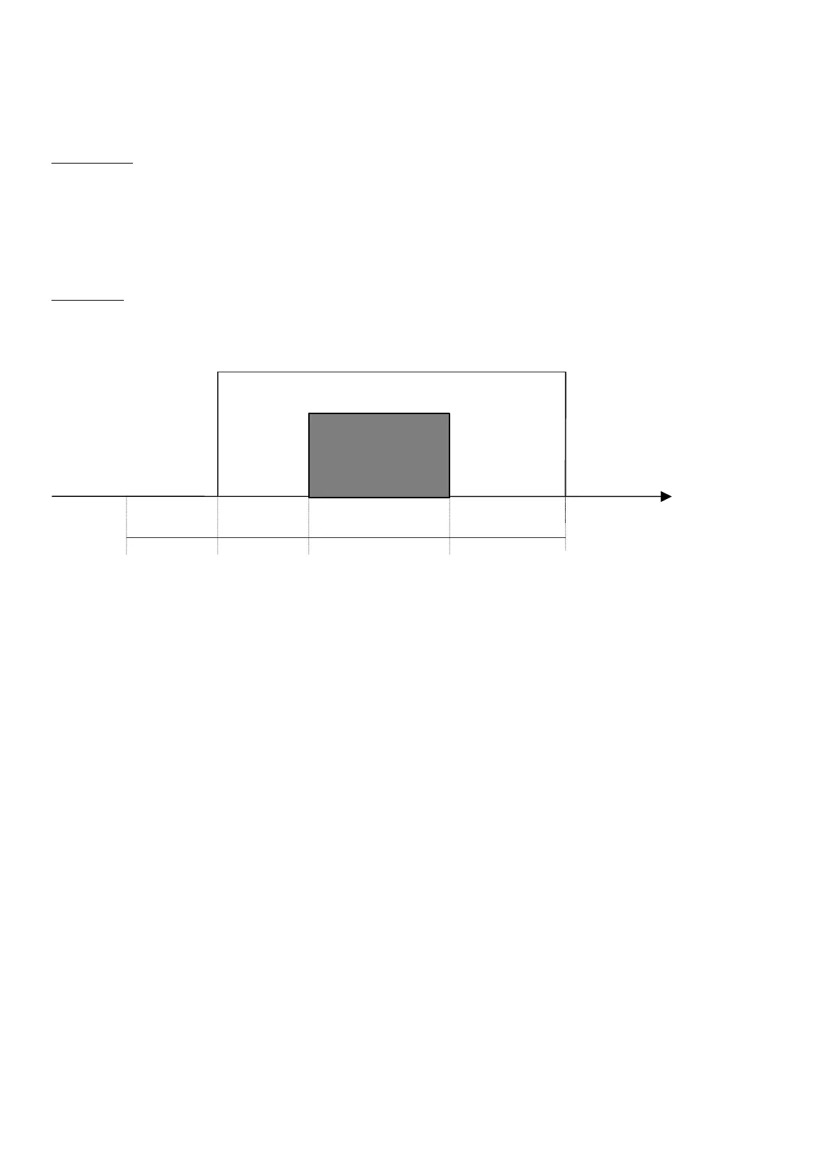
11.5.1 Control of continuous capacity control according to points in the graph
According to the set-point values, the control band with control at output and the neutral zone of compressors on continuous capacity control,
points C, D and E are identified.
If the water temperature measured by the probe located at evaporator outlet exceeds point E
Point E = Control Set-point + Control Band with Control at Outlet
In this case, there is a request for the compressors to be powered up and for power to be increased according to the maximum duration charging
impulses until compressor maximum charging time is reached.
If the water temperature measured by the probe located at evaporator outlet is below point B
Point B = Control Set-point
In this case, there is a request for the compressors to be discharged according to the maximum duration impulses until compressor maximum
discharging time is reached and until possible power-down.
If the water temperature measured by the probe located at evaporator outlet is within the range D-E/B-C
Point D = Control Set-point + (Control Band with Control at Outlet – Neutral Zone for Continuous Capacity control Compressors)
Point C = Point D - Neutral Zone for Continuous Capacity Control Compressors
Then the power of the compressor will be increased/reduced by impulses of variable duration according to the values calculated within the
minimum and maximum limits set for an infinite time.

 Loading...


