Standard Chiller/HP modulare per compressore a vite con driver CAREL
Cod.: +030221241 Rel. 1.0 dated 25 September 03
4
2 THE USER TERMINAL
The specified terminal has an LCD display (4 lines over 20 columns) and can be of two types: on board a built-in card with only 6 keys or
external (connected by telephone cable) with 15 keys. All operations possible with the program can be carried out with both types. With the user
terminal you can view the unit's operating conditions at all times and modify parameters. The terminal can be disconnected from the basic card -
in fact it need not be present at all.
2.1.1 BELOW-KEY LEDS
Three LEDs are located under the rubber keys of the EXTERNAL terminal, and four under the keys of the Built-in card. They respectively
indicate the following:
ON/OFF key (External display) When green the LED indicates that the unit is ON; it flashes in OFF status from the supervisor or
remote digital input
ENTER key (External display) Yellow LED: the instrument is correctly powered
ALARM key (common) Red LED - alarms are present
ENTER key (Built-in display) Yellow LED: see ON/OFF Key (external display)
PROG key (Built-in display) Green LED: you are in a branch of masks, other than the Menu
ESC key (Built-in display) Green LED: you are in the Menu masks branch
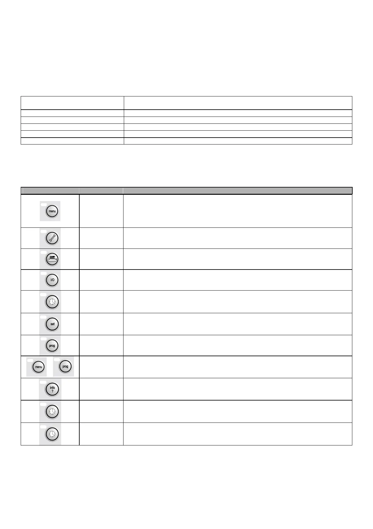
2.1.2 EXTERNAL DISPLAY
How to use the keys on the external terminal
Key Description
MENU
if pressed in all loops except Costr., you return to the main mask of the Menu (MU) branch
if pressed in the Constructor loops, you return to the mask selected by the constructor
The Menu branch displays the status of the unit, the reading of the control probes, and the current
type of operation indicated by CH or HP (meaning chiller or heat pump respectively) in the
bottom right corner).
SERVICING
Sends you to the first screen of the Maintenance loop (A0)
The maintenance loop makes it possible to check the state of the devices and probes, and to
maintain and adjust them, and to run the Manual procedure
PRINTER
Temporary display of the pLAN address of the displayed card
INPUTS
AND OUTPUTS
Sends you to the first mask of the I/O loop (I0)
The I/O loop displays the state of the digital and analogue inputs and outputs
CLOCK
Sends you to the first screen of the Clock loop (K0)
The clock loop is used for displaying / programming time and date
SET-POINT
Sends you to the screen for setting the temperature set-points (SU)
The loop displays and sets also the winter operation set-point.
PROGRAM
Sends you to the screen for inputting the user password (PU)
The user loop is used for displaying / programming the unit's parameters
+
MENU+PROG
Sends you to the mask for inputting the constructor's Password (ZU)
The constructor loop enables configuration of type of unit and selection of connected devices and
enabled functions.
INFO
If pressed in the shared terminal, it switches the displayed card
RED With the unit OFF, it enables winter operation in machine configurations 4 and 5.
BLUE With the unit OFF, it enables summer operation in machine configurations 4 and 5.

 Loading...


