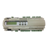
Standard Chiller/HP modulare per compressore a vite con driver CAREL
Cod.: +030221241 Rel. 1.0 dated 25 September 03
23
10.2 Outlet temperature control
Inputs used:
• Water temperature at evaporator outlet
Parameters used:
• Type of unit
• Total number of compressors
• Type of compressor capacity control
• Number of capacity control steps
• Control set-point
• Control band for control at outlet
• Delayed starting of compressor capacity control stages
• Devices activation delay
• Devices disablement delay
• Summer limit of temperature at outlet (powers down all compressors without observing the disabling time)
• Winter limit of temperature at outlet (powers down all compressors without observing the disabling time)
Outputs used :
• Liquid Solenoid
• Windings for compressor Line - Delta - Star
• All compressor capacity control relays
Temperature at
outlet
Request to disable
compressors
Request to enable
compressors
Set point
Neutral band
Neutral zone
Point B
Point A
A neutral temperature zone is identified, based on the set set-point and band values.
Temperature values between set-point and set-point + band (A <
Temperature < B) will not cause enabling or disabling of the compressors.
Temperature values exceeding set-point and set-point + band ( Temperature > point B) will not cause enabling of the compressors.
Temperature values below set-point and set-point + band ( Temperature< point A) will not cause disabling of the compressors.
A temperature threshold, subdivided into summer and winter operation is also specified: the installed devices are unconditionally disabled
above/below this threshold, in order to prevent the units producing too much cold/heat.
10.3 Control of water /water chiller only units
Inputs used:
• Water temperature at evaporator inlet
• Water temperature at evaporator outlet
• Water temperature at condenser inlet
• Water temperature at condenser outlet
Parameters used
:
• Type of unit
• Total number of compressors
• Type of compressor capacity control
• Number of capacity control steps
• Control set-point
• Control band
• Type of control (inlet - outlet)
• Type of control at inlet (proportional - proportional + integral)
• Integration time (if the proportional + integral control is enabled)
• Delayed starting of compressor capacity control stages
• Devices activation delay
Outputs used :
• Liquid Solenoid
• Windings for compressor Line - Delta - Star
• All compressor capacity control relays
10.3.1 Description of operation :
Activation of compressors is controlled by the water temperature measured by the probe located at evaporator inlet/outlet. No condensation fans
are supplied because the condenser is water-cooled.

 Loading...