Standard Chiller/HP modulare per compressore a vite con driver CAREL
Cod.: +030221241 Rel. 1.0 dated 25 September 03
39
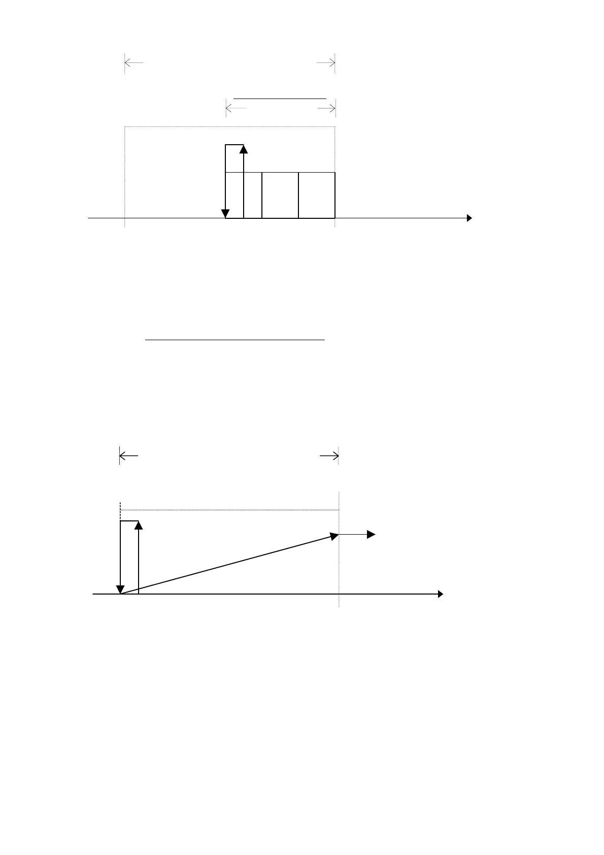
19.6.2 Proportional + integral control
Free Cooling Differential
5.0 %
V1
V2
V3
Free Cooling ON/OFF
Valve
Evaporator Outlet Temperature
Free Cooling set point
Free Cooling Differential
2
Here is an example of Free Cooling control with ON/OFF valve and three condensation steps.
The devices, whether they are valve or fans, will be activated in the second half of the control differential through the effect of the integrating
control. Their activation will be tied to the set integrating constant: the slower it is, the greater the value attributed to the specific parameter.
The amplitude of the valve control step will be 5.50% of the said control differential.
The amplitude of the fan control steps will be calculated according to the following relation:
Step amplitude = Free Cooling Differential
(Number of Master fans X number of cards)
It is assumed that all the circuits controlled by the pCO cards making up the system are equivalent and that the number of controlled devices is
the same.
19.7 Free Cooling ON/OFF valve with inverter controlled condensation
19.7.1 Proportional control
Outlet Evaporator
Temperature
Free Cooling Differential
5.0 %
0 Volt
10 Volt
Free Cooling
ON/OFF Valve
Free Cooling set point
Inverter Ramp 0
to10 V
The ON/OFF valve activation step will, in any case, be positioned in the first part of the control differential and will have an amplitude of 5.0%
of the said differential.
The proportional ramp for piloting the analogue control output of the condensation inverter will be calculated on the entire control differential.
If necessary, Value 0-10 Volt can be further limited downward according to the minimum output voltage value set on the screen.
All proportional outputs relating to the different units of the system will be piloted in parallel

 Loading...


