Standard Chiller/HP modulare per compressore a vite con driver CAREL
Cod.: +030221241 Rel. 1.0 dated 25 September 03
27
11.4 Continuous capacity control
A maximum number of four compressors are managed, with continuous capacity control.
The compressor's capacity is controlled by two relay outputs, which, when suitably controlled, enable compressor power to be increased or
reduced, varying the capacity of the compression chamber.
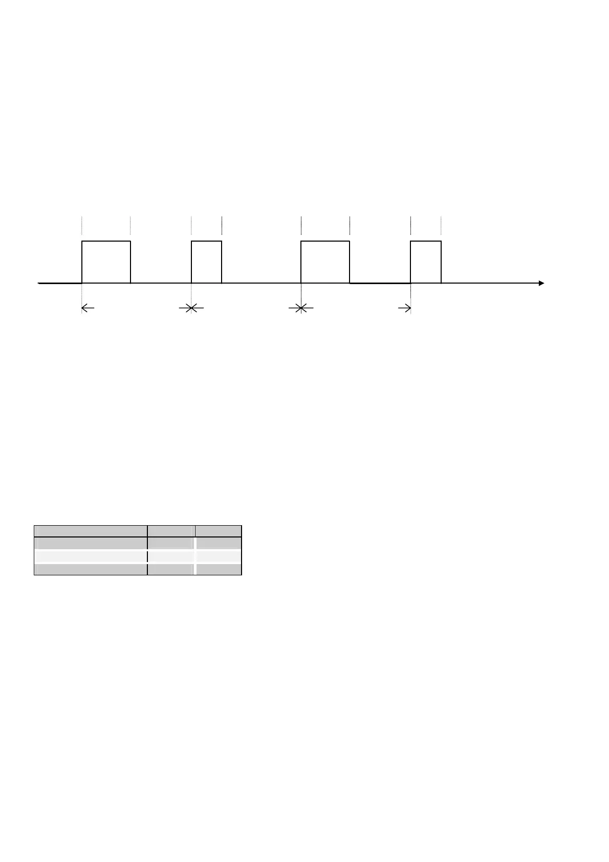
Compressor power is controlled by sending impulses to the outputs of the capacity control relays. These impulses command the compressor to
be charged or discharged.
These impulses are at a constant frequency, settable, and of variable duration between two minimum and maximum limits, also settable.
As there is no acquisition regarding the absolute position of the compressor 's capacity control valve, and, consequently, as no direct verification
is possible of the power percentage input in the circuit, a time based control is run. With this control, when a set time threshold is reached, the
compressor is considered fully charged/discharged and thus control of the capacity control impulses is suspended.
Impulse
calculated
duration
Impulse period
Impulse period
Impulse period
Impulse
calculated
duration
Impulse
calculated
duration
Impulse
calculated
duration
Time [s]
11.4.1 Configuration of continuous capacity control relays
The control method of the capacity control relays differs for each compressor. Therefore, the software has a facility for configuring the enabling
sequence according to the needs of different compressor manufacturers.
For multi-card systems: as several compressors are housed on the same machine, it is considered that the compressors controlled by each pCO
are perfectly equal and, therefore, the capacity control configuration selected on board the master card also applies to the slave cards.
The following table shows examples of the configuration of the dedicated digital outputs for the different power stages entered.
The effective status of the digital output is indicated.
The relation between the data in the table and the values set on the display.
Closed = ON
Open = OFF
Default configuration :
Compressor behaviour Relay 1 Relay 2
Power reduction
CLOSED CLOSED
Power stand-by
OPEN CLOSED
Power increase
OPEN OPEN
The power stand-by configuration is taken on by the outputs when no variation of input power is requested, or if the maximum/minimum
compressor power is reached, or because the water temperature measured by the probe located at evaporator outlet is inside the neutral control
zone.
For compressor charging /discharging, the digital outputs of the pCO card are commanded alternatively according to the stand-by and
charge/discharge configuration, causing the dedicated relay to pulse.

 Loading...


