Standard Chiller/HP modulare per compressore a vite con driver CAREL
Cod.: +030221241 Rel. 1.0 dated 25 September 03
9
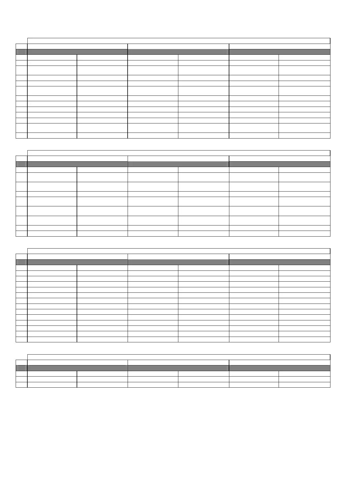
6.2 CHILLER UNIT + HEAT PUMP – MACHINE TYPE “1”
6.2.1 DIGITAL INPUTS
Chiller unit + heat pump MACHINE TYPE “1”
N. pCO2 MEDIUM pCO1 MEDIUM pCOC MEDIUM
Master (Address 1) Slave (addresses 2/3/4) Master (Address 1) Slave (addresses 2/3/4) Master (Address 1) Slave (addresses 2/3/4)
1
Serious alarm (enablable) Serious alarm (enablable) Serious alarm (enablable) Serious alarm (enablable) Serious alarm (enablable) Serious alarm (enablable)
2
Evaporator Flow-switch
(enablable)
Evaporator Flow-switch
(enablable)
Evaporator Flow-switch
(enablable)
Evaporator Flow-switch
(enablable)
Evaporator Flow-switch
(enablable)
Evaporator Flow-switch
(enablable)
3
Remote ON/OFF Remote ON/OFF Remote ON/OFF Remote ON/OFF Remote ON/OFF Remote ON/OFF
4
Pump Thermal cutout Pump Thermal cutout Pump Thermal cutout
5
Low Pressure Pressure-
switch 1
Low Pressure Pressure-
switch 2
Low Pressure Pressure-
switch 1
Low Pressure Pressure-
switch 2
Low Pressure Pressure-
switch 1
Low Pressure Pressure-
switch 2
6
Differential / Oil Level Differential / Oil Level Differential / Oil Level Differential / Oil Level Differential / Oil Level Differential / Oil Level
7
Phase Monitor (enablable) Phase Monitor (enablable) Phase Monitor (enablable) Phase Monitor (enablable) Phase Monitor (enablable) Phase Monitor (enablable)
8
Double Set-point Double Set-point Double Set-point
9
Fan 1 Thermal cutout Fan 1 Thermal cutout Fan 1 Thermal cutout Fan 1 Thermal cutout Fan 1 Thermal cutout Fan 1 Thermal cutout
10
Summer / Winter Summer / Winter Summer / Winter
11
High Pressure Pressure-
switch
High Pressure Pressure-
switch
High Pressure Pressure-
switch
High Pressure Pressure-
switch
High Pressure Pressure-
switch
High Pressure Pressure-
switch
12
Compressor Thermal cutout Compressor Thermal cutout Compressor Thermal cutout Compressor Thermal cutout Compressor Thermal cutout Compressor Thermal cutout
6.2.2 ANALOGUE INPUTS
Chiller unit + heat pump MACHINE TYPE “1”
N. pCO2 MEDIUM pCO1 MEDIUM pCOC MEDIUM
Master (Address 1) Slave (addresses 2/3/4) Master (Address 1) Slave (addresses 2/3/4) Master (Address 1) Slave (addresses 2/3/4)
1
Water temperature at
Evaporator Inlet
High Pressure High Pressure Water temperature at
Evaporator Inlet
2
Water temperature at
Evaporator Outlet
Water temperature at
Evaporator Outlet
Low Pressure Low Pressure Water temperature at
Evaporator Outlet
Water temperature at
Evaporator Outlet
3
Delivery Temperature Delivery Temperature Delivery Temperature Delivery Temperature Condenser Temperature Condenser Temperature
4
Voltage / Current / External
Set-point
Voltage / Current
5
Condenser Temperature Condenser Temperature Water temperature at
Evaporator Inlet
Voltage / Current / External
Set-point
Voltage / Current
6
Voltage / Current / External
Set-point
Voltage / Current Water temperature at
Evaporator Outlet
Water temperature at
Evaporator Outlet
Delivery Temperature Delivery Temperature
7
High Pressure High Pressure Condenser Temperature Condenser Temperature High Pressure High Pressure
8
Low Pressure Low Pressure Low Pressure Low Pressure
6.2.3 DIGITAL OUTPUTS
Chiller unit + heat pump MACHINE TYPE “1”
N. pCO2 MEDIUM pCO1 MEDIUM pCOC MEDIUM
Master (Address 1) Slave (addresses 2/3/4) Master (Address 1) Slave (addresses 2/3/4) Master (Address 1) Slave (addresses 2/3/4)
1
Circulation Pump Circulation Pump Circulation Pump
2
Line Contactor Line Contactor Line Contactor Line Contactor Line Contactor Line Contactor
3
Star Contactor Star Contactor Star Contactor Star Contactor Star Contactor Star Contactor
4
Triangle Contactor Triangle Contactor Triangle Contactor Triangle Contactor Triangle Contactor Triangle Contactor
5
Liquid Solenoid Liquid Solenoid Liquid Solenoid Liquid Solenoid Liquid Solenoid Liquid Solenoid
6
Capacity Control Relay 1 Capacity Control Relay 1 Capacity Control Relay 1 Capacity Control Relay 1 Capacity Control Relay 1 Capacity Control Relay 1
7
Capacity Control Relay 2 Capacity Control Relay 2 Capacity Control Relay 2 Capacity Control Relay 2 Capacity Control Relay 2 Capacity Control Relay 2
8
Capacity Control Relay 3 Capacity Control Relay 3 Capacity Control Relay 3 Capacity Control Relay 3 Capacity Control Relay 3 Capacity Control Relay 3
9
Liquid inj./Econ/Oil Cooler Liquid inj./Econ/Oil Cooler Liquid inj./Econ/Oil Cooler Liquid inj./Econ/Oil Cooler Liquid inj./Econ/Oil Cooler Liquid inj./Econ/Oil Cooler
10
Antifreeze Heater Antifreeze Heater Antifreeze Heater Antifreeze Heater Antifreeze Heater Antifreeze Heater
11
General Alarm General Alarm General Alarm General Alarm General Alarm General Alarm
12
4-wayValve 4-wayValve 4-wayValve 4-wayValve 4-wayValve 4-wayValve
13
Fan 1 Fan 1 Fan 1 Fan 1 Fan 1 Fan 1
6.2.4 ANALOGUE OUTPUTS
Chiller unit + heat pump MACHINE TYPE “1”
N. pCO2 MEDIUM pCO1 MEDIUM pCOC MEDIUM
Master (Address 1) Slave (addresses 2/3/4) Master (Address 1) Slave (addresses 2/3/4) Master (Address 1) Slave (addresses 2/3/4)
1
2
Speed Controller Speed Controller Speed Controller Speed Controller Speed Controller Speed Controller

 Loading...


