13
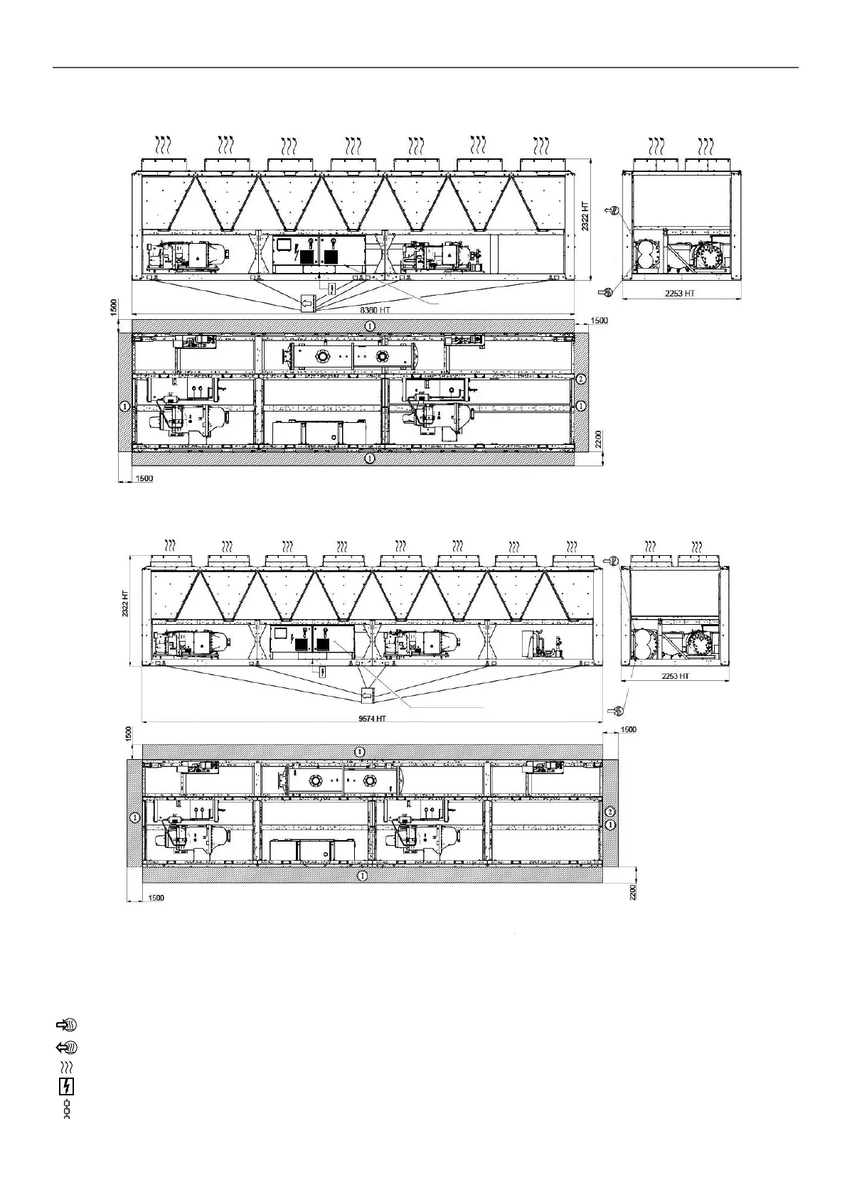
3.5 - 30XB 1000, 30XBE 900, 30XBP 850 to 900, 30XB 750 to 850 option 254/255, 30XB 850 to 900 50
or 118A, 30XB 900 option 119 (high eciency), 30XBE 850 option 50 or 118A
POWER AND CONTROL ELECTRICAL BOX
3.6 - 30XBE1000, 30XBP1000, 30XB-900 option 254/255, 30XB-1000 option 50 or 118A or 119
POWER AND CONTROL ELECTRICAL BOX
Legend
All dimensions are given in mm.
NOTES:
- Drawings are not contractually binding.
- Refer to unit nameplate for unit weight information
- Before designing an installation, consult the certified
dimensional drawings, provided with the unit (Appedix 4).
- If the installation includes several units or if this (these) is
(are) close to walls, please refer to chapters 3.13 - “Multiple
chiller installation” and 3.14 - “Distance to the wall” of the
installation manual to determine the space required
B
Required clearances for maintenance (see note)
C
Recommended space for evaporator tube removal
Water inlet for standard unit - for options 100A, 100C, 107 refer to the certied
drawing.
Water outlet for standard unit - for options 100A, 100C, 107 refer to the certied
drawing.
Air outlet – do not obstruct
Power supply and control connection
Slinging points
3 - DIMENSIONS, CLEARANCES

 Loading...


