45
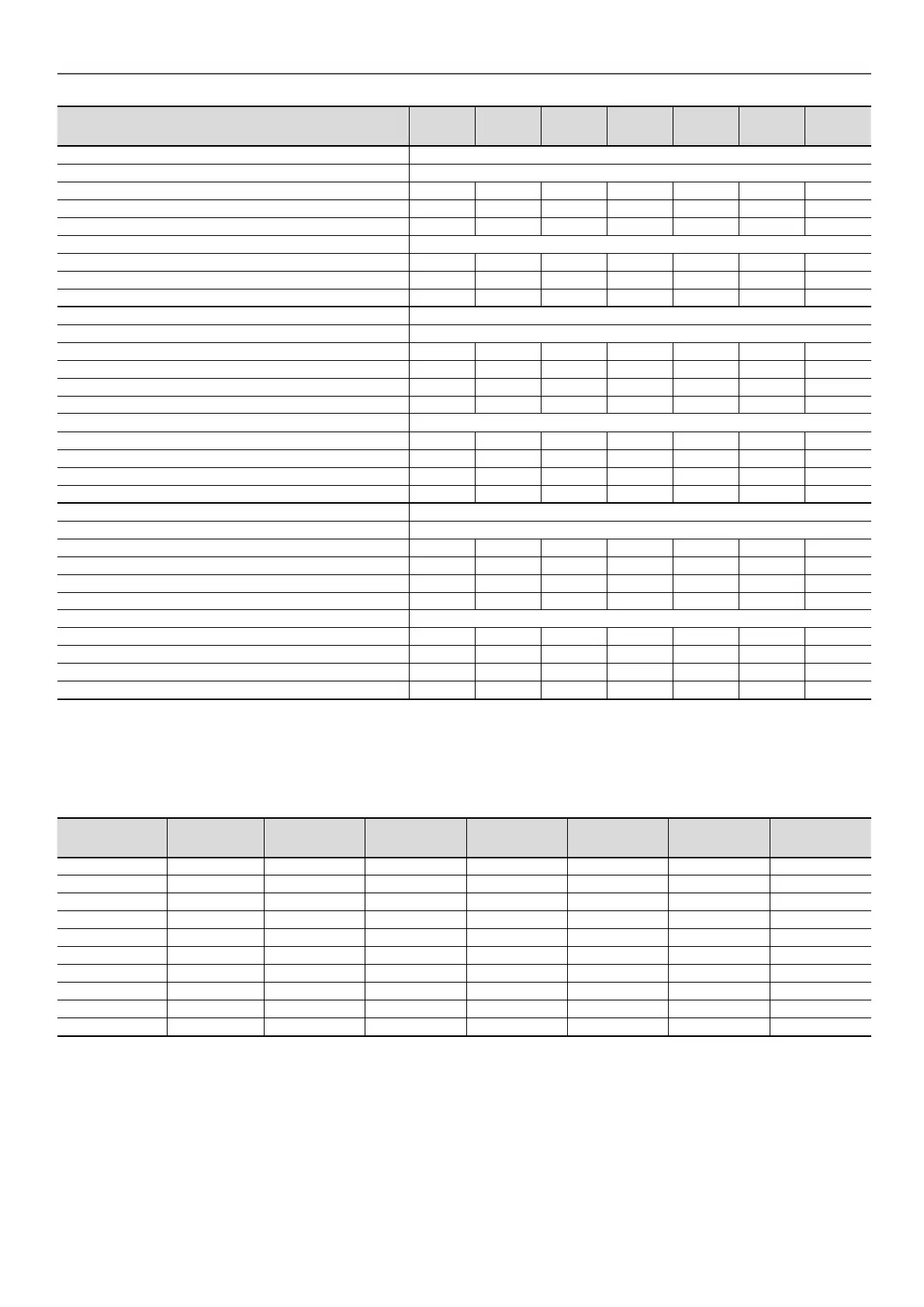
30XB 1100 1200 1300 1400 1500 1550 1700
Maximum current (Un-10%)
(1)
- 30XB
Standard unit
Circuit 1
(a)
A 341 390 474 506 538 780 633
Circuit 2
(a)
A 510 541 506 534 538 390 633
Option 081 A 850 931 979 1039 1075
Unit + option 15LS
Circuit 1
(a)
A 331 380 458 490 521 756 611
Circuit 2
(a)
A 496 524 490 518 521 378 611
Option 081 A 826 904 948 1008 1041
Nominal start-up current
(3)
- 30XB
Standard unit
Circuit 1
(a)
A 587 587 629 629 629 828 759
Circuit 2(
a)
A 629 629 629 629 629 587 759
Option 081 A 936 976 982 1014 1018
Option 081 & Opt 25c A 687 702 729 744 744
Unit + option 15LS
Circuit 1
(a)
A 587 587 629 629 629 828 740
Circuit 2
(a)
A 629 629 629 629 629 587 740
Option 081 A 922 959 966 998 1001
Option 081 & Opt 25c A 674 685 714 729 727
Maximum start-up current(Un)
(2)
- 30XB
Standard unit
Circuit 1
(a)
A 587 587 629 629 629 828 813
Circuit 2
(a)
A 629 629 629 629 629 587 813
Option 081 A 1051 1094 1097 1132 1136
Option 081 & Opt 25c A 802 820 844 862 862
Unit + option 15LS
Circuit 1
(a)
A 587 587 629 629 629 828 805
Circuit 2
(a)
A 629 629 629 629 629 587 805
Option 081 A 1037 1077 1081 1116 1119
Option 081 & Opt 25c A 789 803 829 847 845
(1) Values obtained at unit continuous maximum operating conditions (data given on the unit nameplate)
(2) Operating current of the smallest compressor(s) + fan current + locked rotor current or reduced start-up current of the largest compressor.
(3) Standardised EUROVENT conditions, water-cooled exchanger water inlet/outlet = 12°C/7°C, outdoor air temperature = 35°C.
(a) When the machines are equipped with two power supplies, circuit 1 supplies the refrigerant circuit A and circuit 2 supplies the refrigerant circuit B or for units 30XB1550
to 1700 units: Circuit 1 supplies circuits A and B, circuit 2 supplies circuits C and D.
4.7 - Compressor electrical data
Compressor I Nom
(1)
I Max
(Un)
(2)
I Max
(Un - 10%)
(3)
LRYA
A
(4)
LRDA
A
(5)
Cos
Phi nom.
(6)
Cos
Phi Max.
(7)
06TSA155 64 93 99 170 530 0,87 0,9
06TSA186 80 111 118 170 530 0,86 0,89
06TTA266 117 162 172 303 945 0,86 0,9
06TTA301 132 177 188 388 1210 0,87 0,9
06TTA356 153 207 220 388 1210 0,87 0,9
06TUA483 225 292 311 587 1828 0,87 0,88
06TUA554 241 338 360 587 1828 0,88 0,89
06TVA680 302 400 436 629 1919 0,87 0,89
06TVA753 315 430 468 629 1919 0,88 0,89
06TVA819 347 465 496 629 1919 0,88 0,89
Legend
(1) Nominal current draw at standard Eurovent conditions (see denition of conditions under nominal unit current draw)
(2) Maximum operating current
(3) Maximum compressor operating current, limited by the unit (current given for maximum capacity at 360 V)
(4) Locked rotor current for star connection (connection during compressor start-up)
(5) Locked rotor current for delta connection
(6) Value at standard Eurovent conditions: evaporator entering/leaving water temperature 12°C/7°C, condenser entering/leaving water temperature 30°C/35°C.
(7) Value at maximum capacity and nominal voltage
4 - PHYSICAL AND ELECTRICAL DATA FOR 30XB UNITS

 Loading...


