79
14.4 - Tightening torques for the main electrical
connections
14.4.1 - Tightening torques for the main electrical
connections
Component
Designation
in the unit
Value
(N.m)
Screw on bus bar, customer connection
M8 - 18
M10 L1 /L2 /L3 30
Soldered screw PE, customer connection
(M12)
PE 70
Tunnel terminal screw, compressor
contactor
Contactor 3RT103_
Contactor 3RT104_ 5
Contactor 3RT105_ 11
Contactor 3RT106_ KM_ 21
Nut on compressor contactor deck
M8 for contactor 3RT105_ 18
M10 for contactor 3RT10_7 KM_ 30
Tunnel terminal screw, current transformer
Size 2 (3RB2956_) 11
Size 3 (3RB2966_) TI_ 21
Nut on current transformer deck
M8 18
M10 TI_ 30
Compressor earth terminal in the power
wiring control box
Terminal M8 Gnd 30
Compressor phase connection terminals
M12 25
M16 EC_ 30
Compressor earth connection Gnd sur EC_ 25
Tunnel terminal screw, disconnects
3RV1011_
QF_ /QM_ 1
Tunnel terminal screw, hydronic pump
contactor
Contactor 3RT101_ KM90_ 1
Contactor 3RT102_ 2,2
ATTENTION: The tightening of the connections at the
compressor terminals requires special precautions. Please
refer to the chapter below.
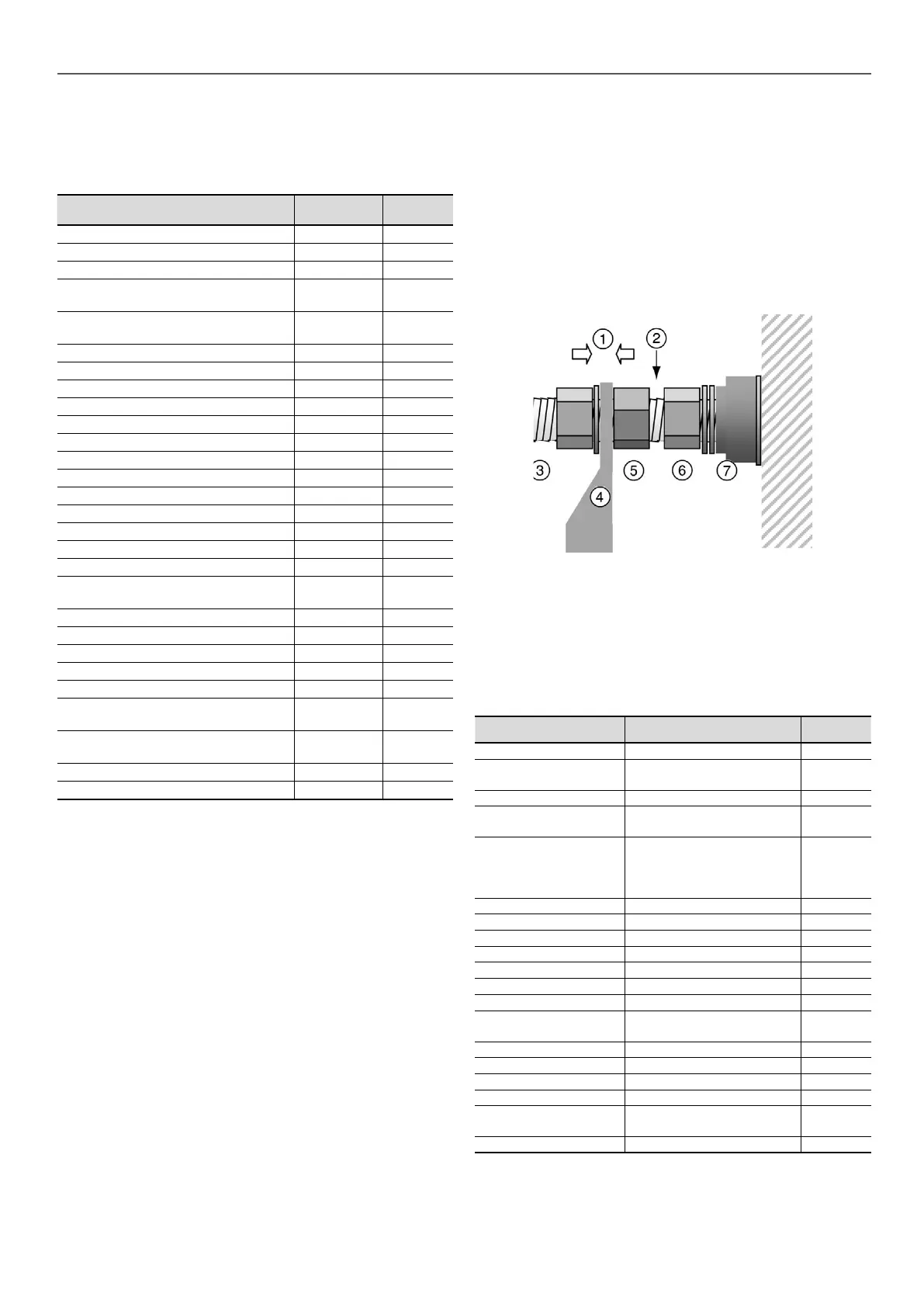
14.4.2 - Connection precautions for the compressor
power terminals
These precautions must be applied during an intervention that
requires the removal of the power conductors connected to the
compressor supply terminals.
The tightening nut of terminal (6) supporting the isolator (7) must
never be loosened, as ist ensures terminal tightness and
compressor leak tightness.
The tightening of phase lug (4) must apply the torque between counter
nut (5) and tightening nut (3): During this operation a counter-torque
must be applied at counter nut (5). Counter-nut (5) must not be in
contact with the tightening nut of terminal (6).
1. Torque application to tighten the lug
2. Avoid contact between the two nuts
3. Lug tightening nut
4. Flat lug
5. Counter-nut
6. Terminal tightening nut
7. Isolator
14.5 - Tightening torques for the main bolts and
screws
Screw type Use
Value (N.m)
(N·m)
Metal screw D = 4,8
Condensing module, housing
supports
4,2
Metal screw D = 6,3 Plastic volute & grill 4,2
Screw H M8
Condensing module,
compressor xing
18
Taptite screw M10
Condensing module, chassis
- structure xing, control box
xings, compressor xings, oil
separator xing
30
Taptite screw M6 Piping support, cowling 7
Screw H M8 Piping clip 12
Screw H M6 Piping clip 10
Nut H M10 Compressor chassis 30
Nut H M10 Hydraulic pump chassis 30
Screw H M8 Filter drier cover 35
Screw H M12 Economiser port ange 40
Screw H M16
Oil separator anges, suction
anges
110
Screw H M16 Heat exchanger water boxes 190
Screw H M20 Suction anges 190
Nut 5/8 ORFS Oil line 65
Nut 3/8 ORFS Oil line 26
Nut H M12/M16
Victaulic collars on suction
piping
60/130
Self-locking Nut M16 Compressor xing 30
ATTENTION: The tightening of the connections at the
compressor terminals requires special precautions. Please
refer to the chapter below.
14 - STANDARD MAINTENANCE

 Loading...


