50
5.6 - Field control wiring
IMPORTANT: Field connection of interface circuits may lead
to safety risks: Any control box modication must maintain
equipment conformity with local regulations. Precautions
must be taken to prevent accidental electrical contact between
circuits supplied by dierent sources:
- The routing selection and/or conductor insulation
characteristics must ensure dual electric insulation.
- In case of accidental disconnection, conductor xing
between dierent conductors and/or in the control box
prevents any contact between the conductor ends and
an active energised part.
Refer to the SmartVu
TM
control manual and the certied wiring
diagram supplied with the unit for the eld control wiring of the
following features:
- Remote on/o switch
- Demand limit external switch
- Remote dual set point
- Alarm, alert and operation report
- Evaporator pump control
- Heat reclaim condenser pump control (option)
- Hot water valve control (option)
- Set point reset via outside air temperature sensor reset
- Various interlocks on the Energy ManagementModule (EMM)
board (option).
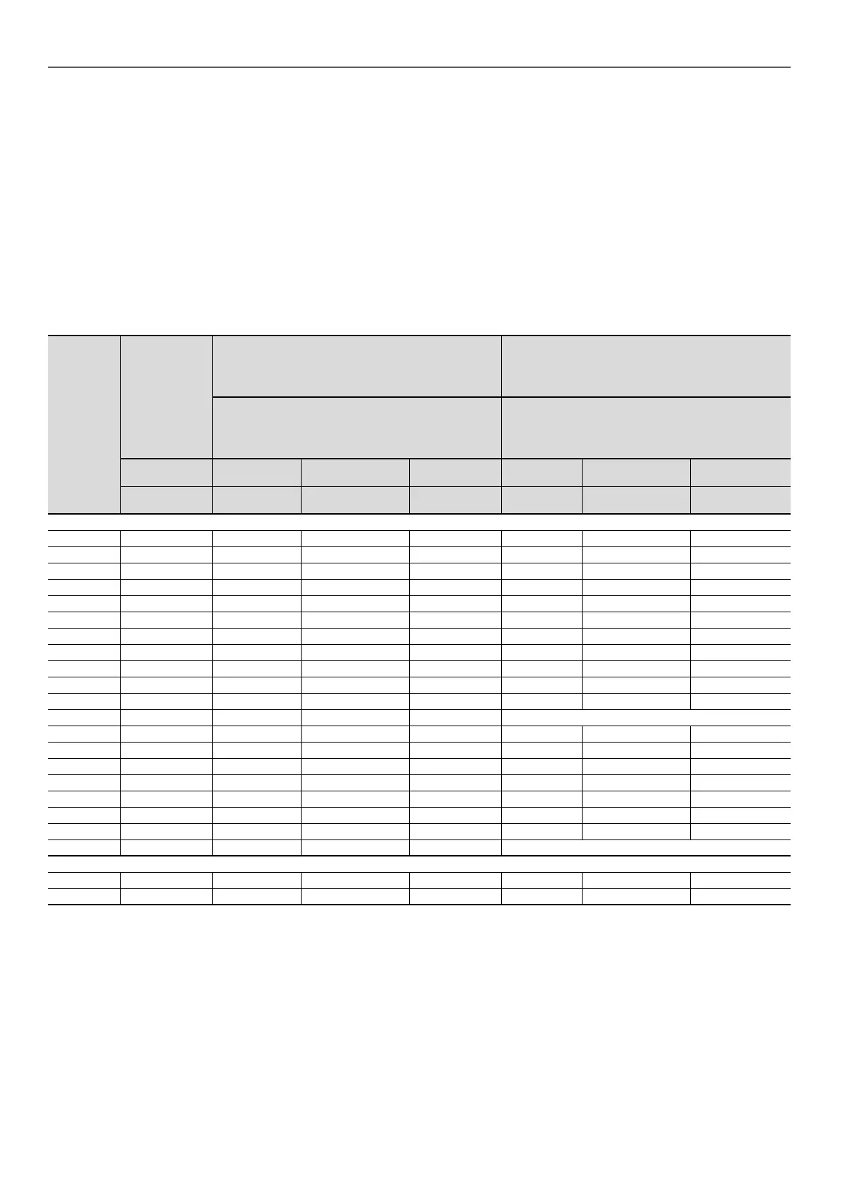
Selection of minimum and maximum wire sections for connection to 30XB(E/P) units
30XB
30XBE
30XBP
Max.
connectable
wire section
(1)
Calculation of favourable case:
-Suspended overhead/aerial line (standardised
routing no. 17)
-90°C insulated cable
- Copper conductor (Cu)
Calculation of unfavourable case:
- Conductors in ducts or multi-conductor cables in
closed conduit (standardised routing No. 41)
-70°C insulated cable if possible
- Copper conductor (Cu)
Calculation of favourable case:
- Perforated horizontal conduit (standardised routing
No. 13/15)
- 90°C insulated cable
- Copper conductor (Cu)
Calculation of unfavourable case:
- Closed conduit (standardised routing No. 41)
- 70°C insulated cable if possible
- Copper conductor (Cu)
Section
(2)
Max. length for
a voltage drop <5%
Cable type Section
(2)
Max. length for
a voltage drop <5%
Cable type
qty x mm²
(per phase)
qty x mm²
(per phase)
m -
qty x mm²
(per phase)
m -
Standard unit
250 2 × 185 1 x 95 190 XLPE Cu 2 x 95 450 PVC Cu
300 2 × 185 1 x 95 190 XLPE Cu 2 x 95 420 PVC Cu
350 2 × 185 1 x 120 197 XLPE Cu 2 x 95 390 PVC Cu
400 2 × 185 1 x 150 200 XLPE Cu 2 x 120 400 PVC Cu
450 2 × 185 1 x 185 205 XLPE Cu 2 x 150 420 PVC Cu
500 2 × 185 1 x 240 205 XLPE Cu 2 × 185 430 PVC Cu
600 2 × 240 2 x 95 190 XLPE Cu 2 × 240 440 PVC Cu
700 2 × 240 2 x 120 198 XLPE Cu 2 × 185 330 XLPE Cu
750 2 × 240 2 x 120 198 XLPE Cu 2 × 240 370 XLPE Cu
800 2 × 240 2 x 150 200 XLPE Cu 2 × 240 330 XLPE Cu
850 2 × 240 2 x 150 200 XLPE Cu 2 × 240 320 XLPE Cu
900 2 × 240 2 × 185 205 XLPE Cu Not compatible - -
1000 4 × 300 2 × 240 205 XLPE Cu 4 x 185 320 XLPE Cu
1100 2x240/3x240 1x185/2x120 291/240 XLPE Cu 2x240/3x240 600/530 PVC Cu/PVC Cu
1200 2x240/3x240 1x240/2x150 310/270 XLPE Cu 2x150/2x240 380/380 XLPE Cu/XLPE/Cu
1300 2x240/3x240 2x120/2x120 260/240 XLPE Cu 2x240/2x240 420/400 XLPE Cu/XLPE Cu
1400 2x240/3x240 2x120/2x150 240/270 XLPE Cu 2x240/2x240 400/380 XLPE Cu/XLPE Cu
1500 2x240/3x240 2x120/2x150 240/270 XLPE Cu 2x240/2x240 400/380 XLPE Cu/XLPE Cu
1550 4 x 300 /2 x240 2 x 300/1 x 240 300/310 XLPE Cu 4x 240 /2x 150 400/380 XLPE Cu/XLPE Cu
1700 2 x 240 /2 x240 2 x 185/2 x 185 260/260 XLPE Cu Not compatible -
30XB, 30XBE & 30XBP + option 81
1100 to 1500 5x240
1550 8x240
(1) Connection capacities actually available for each machine. These are dened according to the connection terminal size, the electrical/control box access opening
dimensions and the available space inside the electrical/control box.
(2) Selection simulation result considering the hypotheses indicated.
(3) If the maximum calculated section is for an 90°C cable type, this means that a selection based on a 70°C cable type can exceed the connection capacity actually
available. Special attention must be given to selection.
The protection against direct contact at the electrical connection point is compatible with the addition of terminals extension. The installer must determine whether these
are necessary based on the cable sizing calculation.
NOTE: The currents considered are given for a machine equipped with an hydraulic module operating at maximum current.
5 - ELECTRICAL CONNECTION

 Loading...


