52
6.5 - System minimum water volume
Whichever the system, the water loop minimum capacity is given
by the formula:
Capacity = Cap (kW) x N litres
Application N
Normal air conditioning 3,25
Process type cooling 6,5
Where Cap is the nominal system cooling capacity (kW) at the
nominal operating conditions of the installation.
This volume is necessary for stable operation and accurate
temperature control.
It is often necessary to add a buer water tank to the circuit in order
to achieve the required volume. The tank must itself be internally
baed in order to ensure proper mixing of the liquid (water or
brine). Refer to the examples below.
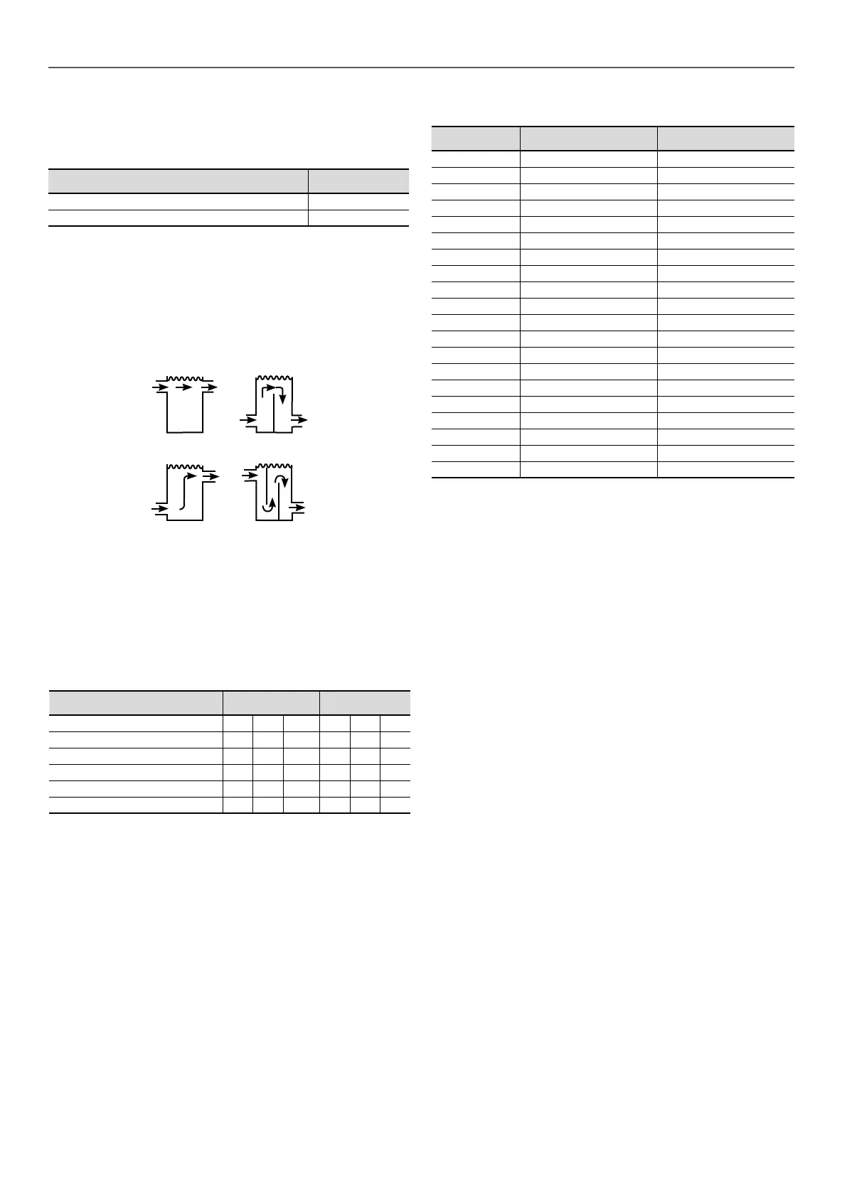
Connection to a buer tank
Bad
Bad
Good
Good
6.6 - Maximum system water volume
Units with hydraulic module incorporate an expansion tank that
limits the water volume. The table below gives the maximum loop
volume for pure water or ethylene glycol with various system
concentrations, as well as the static pressures. If the maximum
volume is insucient, compared to the minimum system water
loop volume, an additional expansion tank must be added to the
system.
30XB(E/P) Sizes 250 to 450 500
Static pressure bar 1 2 2,5 1 2 2,5
Pure water l 2400 1600 1200 3960 2640 1980
10% EG l 1800 1200 900 2940 1960 1470
20% EG l 1320 880 660 2100 1400 1050
30% EG l 1080 720 540 1740 1160 870
40% EG l 900 600 450 1500 1000 750
EG : Ethylene Glycol
6.7 - Evaporator water ow rate
30XB(E/P)
Minimum ow rate
(1)
(l/s) Maximum ow rate
(2)
(l/s)
250 4,6 37,5
300 5,0 40,5
350 5,4 40,5
400 6,5 34,1
450 7,4 36,9
500 8,3 42,0
600 10,4 45,0
700 11,3 56,1
750 12,2 59,1
800 13,1 67,1
850 13,8 67,1
900 15,0 73,9
1000 16,4 83,9
1100 19,1 87,8
1200 21,1 126,5
1300 22,2 92,9
1400 24,0 132,1
1500 25,2 107,4
1550 25,7 109,4
1700 28,1 107,4
(1) Minimum ow rate for optimal eciency in variable ow conguration
(2) Maximum ow rate for a pressure drop of 100 kPa in the exchanger
6 - APPLICATION DATA

 Loading...


