69
11 - UNIT OPERATION WITH A FREE COOLING DRYCOOLER (OPTION_313)
11.1 - Unit operation with a free cooling
drycooler (optional)
11.1.1 - Operating principle
The units have been designed to optimise the operation of systems,
using drycoolers as a free cooling system (method using low outdoor
air temperatures to chill the water in the air conditioning system).
This system allows substantial energy and cost savings, which is
at its most eective when the outdoor air temperature is low.
The unit’s SmartVu
TM
control system includes algorithms which
enable continuous automatic optimisation of the following:
- the operation of the drycooler fans,
- the variation of the ow rate in the water loop,
- the cooling capacity (the drycooler and chiller can operate
independently or simultaneously),
- the positions of the valves, depending on the operating mode.
The control denes the optimal conguration, taking the water
setpoint value, outdoor air temperature, and water loop temperature
into account (the control will give priority to the drycooler).
Parallel control of the fans and of the variable ow rate of the water
loop enable the system to operate at outdoor temperatures of
down to -20°C without any additional control.
Warning: the drycooler and chiller both need to be equipped
with the Free cooling management option.
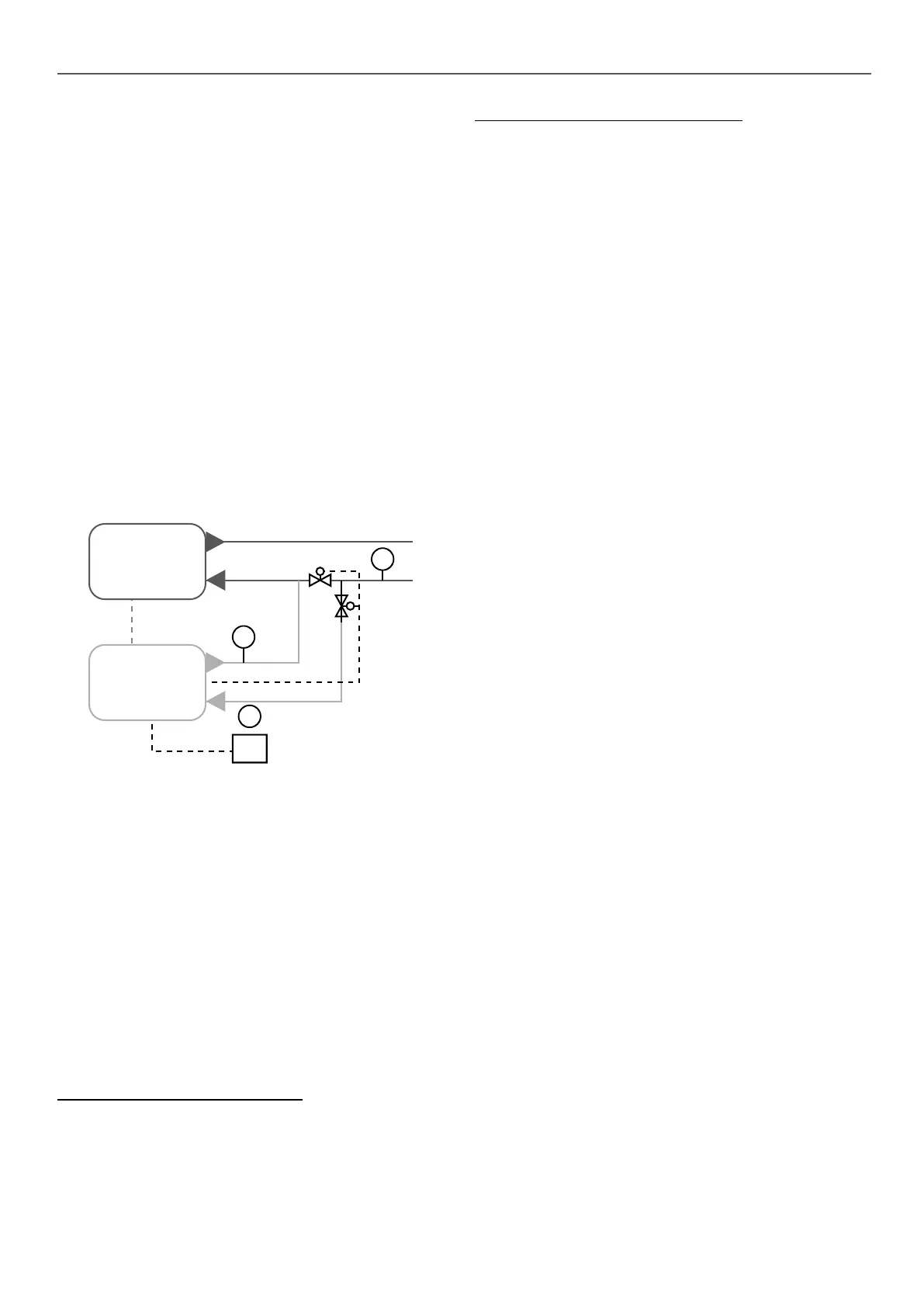
Chiller
NO
NC
DC free cooling
LEN
communication
OAT
V2V control
2
1
3
For an optimal free cooling operation, the chiller has to be
congurated:
- using the water inlet temperature control,
- using the delta temperature control for the variable speed
pump option.
11.1.2 - Communication to control the drycooler
When the option is selected, a specific electronic board is
integrated in the drycooler control panel. An LEN communication
bus connected between the drycooler (AUX1 board) and the chiller
is needed for overall control of the system.
This cable must be a 3-point Wago type cable (5 mm spacing or
equivalent) and must be shielded.
The board integrated in the drycooler control panel has analogue
inputs for the outside air temperature (item 1), water loop return
(item 3), and drycooler water outlet temperature (item 2) sensors,
as well as digital outputs for controlling the fans.
The option works as a system split in two parts:
The chiller (with free cooling option):
Dedicated control algorithms supplied with the LEN connector to
control the drycooler.
The drycooler (with free cooling option):
- AUX board with the I/O
- room air temperature sensor to be placed outdoors,
- drycooler water outlet temperature sensor (factory-tted),
- water loop temperature sensor (to be tted on the common
pipe upstream of the valve),
- Control & 230V power supply for 2 two-way valves or one
three-way valve
The dierence between the drycooler outdoor air temperature and
the water loop sensor temperature determines whether or not it
is possible to activate free cooling mode.
11.1.3 - Conguration of the fan control
To set the conguration corresponding to the drycooler installed
(number of fans, control type – xed or variable speed), please
refer to the instructions in the SmartVu
TM
control manual. Following
these parameters, the SmartVu
TM
control will activate the adequate
number of digital outputs to control the fans.
SmartVu
TM
controls the automatic switching of all fans, based on
operating time and number of start-ups, to ensure the fan motors
provide a long service life.
Compatible fans conguration:
- 1 to 20 fans,
- xed speed or variable speed
- fans in one l or 2 lines
Refer to the drycooler wiring diagram to see the arrangement of
the fan stages.
11.1.4 - Valves on the water loop
The free cooling system requires two two-way valves (one normally
open, one normally closed) or a three-way valve, not supplied with
the unit or the drycooler.
A two-way valve kit is available in the list of accessories for the
drycooler.
The drycooler control panel has a 230 V power supply for two
two-way valves.
Recommended motor valve (per default): 230V 3 points
See the drycooler wiring diagram for cabling the valves to the
customer terminal strip.
11.1.5 - Guidelines for system installation
For the physical properties, dimensions and performances: see
the drycooler documentation.
For the electrical connections, see the electrical wiring diagram
supplied with the drycooler.
For software configuration information, refer to the control
documentation of the chiller.
For correct installation of the drycooler, the rules for calculation
and sizing relating to the following areas must be observed:
- sizing of the water piping;
- pressure drops (check the operating pressure of the unit’s
pump is sucient in relation to the pressure drops in the pipes
and valves - perform this check for all operating modes);
- maximum height of the drycooler (in relation to the unit’s relief
valve);
- suitable positioning of the temperature sensors: outdoor air
temperature and water loop temperature.

 Loading...


