17
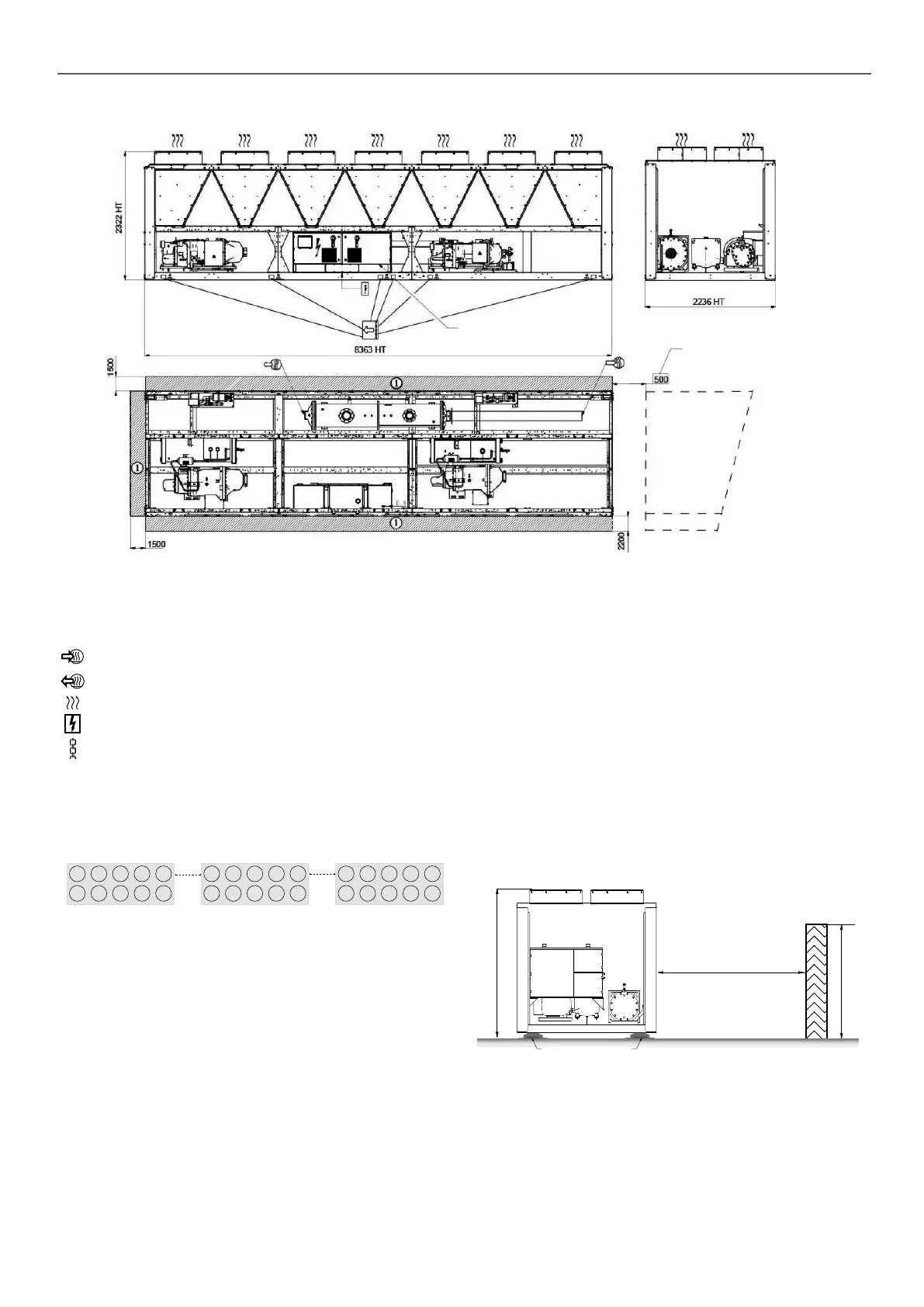
3.13 - 30XB 1700, 30XBE 1700 - module 2/2
POWER AND CONTROL ELECTRICAL BOX
module 1
SPACE REQUIRED BETWEEN
MODULE 1 AND MODULE 2
FOR COILS SERVICE
Legend
All dimensions are given in mm.
NOTES:
- Drawings are not contractually binding.
- Refer to unit nameplate for unit weight information
- Before designing an installation, consult the certified
dimensional drawings, provided with the unit (Appedix 4).
- If the installation includes several units or if this (these) is
(are) close to walls, please refer to chapters 3.13 - “Multiple
chiller installation” and 3.14 - “Distance to the wall” of the
installation manual to determine the space required
B
Required clearances for maintenance (see note)
C
Recommended space for evaporator tube removal
Water inlet for standard unit - for options 100A, 100C, 107 refer to the certied
drawing.
Water outlet for standard unit - for options 100A, 100C, 107 refer to the certied
drawing.
Air outlet – do not obstruct
Power supply and control connection
Slinging points
3.14 - Multiple chiller installation
It is recommended to install multiple chillers in a single row,
arranged as shown in the example below, to avoid recycling of
warm air from one unit to another.
1.5 m
mini
1,5 m
mini
If the situation at the site does not permit this arrangement, contact
your Carrier distributor to evaluate the various possible
arrangements. In certain situations an accessory (supplied loose
at the time of purchase) can be added.
3.15 - Distance to the wall
To ensure correct operation for most cases:
If h < H (2.3 m), minimum S = 3 m
If h > H or S < 3 m, contact your Carrier distributor to evaluate the
various possible arrangements.
H
S
h
Anti-vibration
mounts
3.16 - Underneath a roof
The upper part of the machine (on top of the fans) must not be
covered.
If the oor space requires the machine to be partially covered,
contact your Carrier distributor to assess the various installation
option.
3 - DIMENSIONS, CLEARANCES

 Loading...


