– 58 –
Outdoor header unit (MMY-MAP1204FT
∗
UL) Outdoor follower unit (MMY-MAP1204FT
∗
UL)
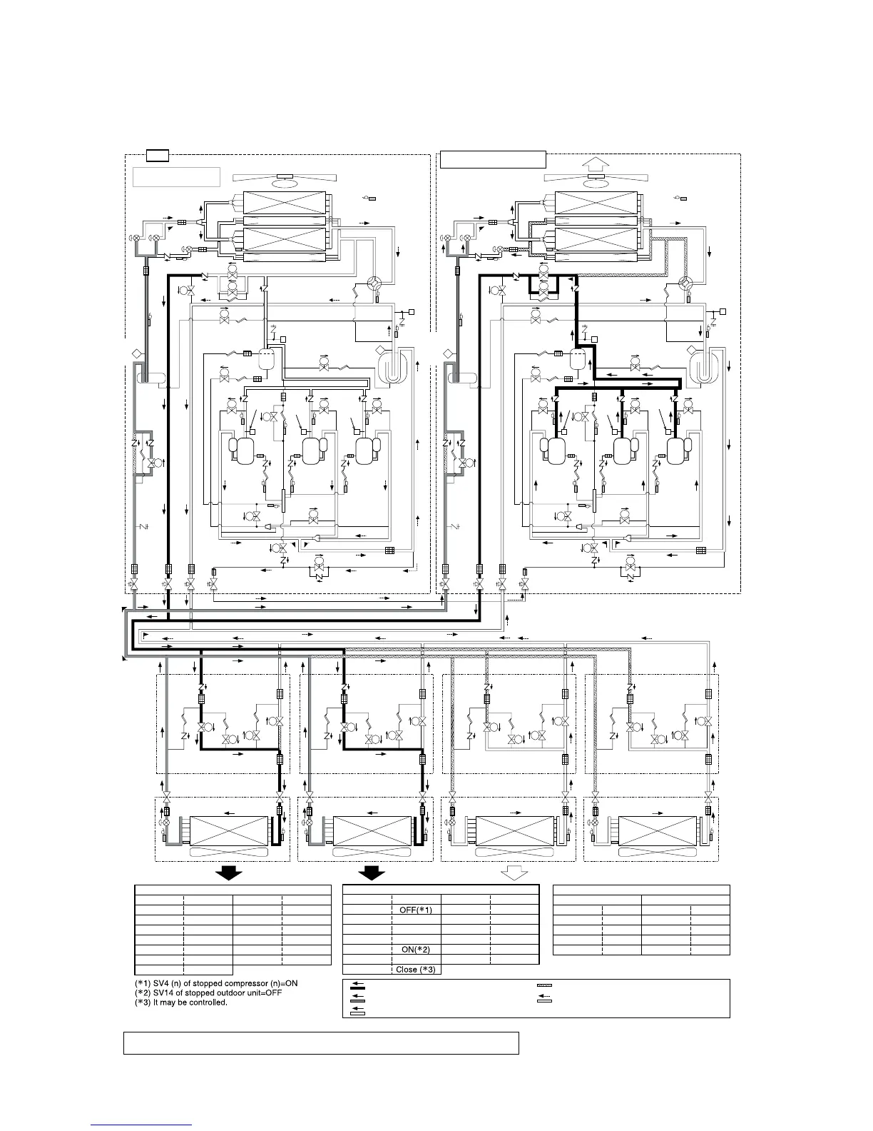
5-7. Emergency operation (All heating operation at backup of the header unit)
PMV1
PMV2
PMV4
TE2
TE1
FM
Fan
Fan motor
TO
Right side
Main
heat exchanger
Main
heat exchanger
Right side sub heat exchanger
Left side
Left side sub heat exchanger
SV5
SV11
SV
SV
SV
SV
SV
SV
SV
SV
SV
SV
SV
SV
SV
SV
SV
SV
SV
SV
SV
SV
SV
SV
PMV1
PMV2
PMV4
TE2
TE1
FM
Fan
Fan motor
TO
Right side
Main
heat exchanger
Main
heat exchanger
Right side sub heat exchanger
Left side
Left side sub heat exchanger
SV11
SV
SV SV
SV
SV
SV
SV
SV
SV
SV
FP
Liquid
tank
Liquid
tank
SV6
TL
TL
SV3D
SV41
High
pressure
SW
High
pressure
SW
High
pressure
SW
Oil
separator
Check joint
( High pressure)
High pressure
sensor
SV42
SV
SV
SV2
SV42
SV
SV2
Comp.
1
(Inverter)
Comp.
2
(Inverter)
Comp.
3
(Inverter)
TD2TD1
TD3
SVD
SVD
SVD
SVD
SVDD
SVDD
SVDD
SVDD
SVSS
SVSS
PMV
SVS
SVS
SVSS
SVS
SVSS
SVS
Check
joint
(Liquid
pipe)
SV14
Balance pipe
Liquid pipe
Dischage gas pipe
Suction gas pipe
TK5
TK3
TK2
TK1
SV3E
SV3A
SV3B
SV
SV
SV3A
SV3B
Oil header
SV3F
SV
SV
TK5
SV3E
Oil header
SV3F
SV14
Check
joint
(Liquid
pipe)
SV3C
SV
SV
SV41
Comp.
1
(Inverter)
Comp.
2
(Inverter)
Comp.
3
(Inverter)
TD2TD1
TD3
TK3
TK2
TK1
SV3C
SV43
SV
SV43
Accumulator
TS2
Low
pressure
sensor
TS1
4-way
valve
FP
TC2
TCJ
TC1
PMV
TC2
TCJ
TC1
PMV
TC2
TCJ
TC1
Stop
Stop
Heating
PMV
TC2
TCJ
TC1
Heating
Indoor unit
FS unit
When PMV leaked, service
valve at liquid side = Close fully
Trouble
Fusible
plug
Check
joint
(Low
pressure)
SV5
SV
SV
SV
SV
SV6
SV3D
Oil
separator
Check joint
( High pressure)
High pressure
sensor
Accumulator
TS2
Low
pressure
sensor
TS1
4-way
valve
Check
joint
(Low
pressure)
Fusible
plug
High
pressure
SW
High
pressure
SW
High
pressure
SW
4-Way valve
SV4(n)
SV5
SV6
SV11
SV14
PMV4
PMV1, 2
OFF
ON
OFF
ON
OFF
OFF
OFF
OFF
ON
ON
Control
ON
OFF
Close
Close
SV3A
SV3B
SV3C
SV3D
SV3E
SV3F
Outdoor fan
Trouble header outdoor unit
Temporal header outdoor unit
4-Way valve
SV4(n)
SV5
SV6
SV11
SV14
PMV4
PMV1, 2
ON
OFF
Control
Control
ON
SV3A
SV3B
SV3C
SV3D
SV3E
SV3F
Outdoor fan
Control
Control
Control
Control
ON
Control
Control
(20 Ton system described in the example of (10 Ton + 10 Ton))
High-pressure gas refrigerant
Condensed liquid refrigerant
Evaporative gas refrigerant (Low pressure)
Pressure circuit (High-pressure refrigerant)
Low-pressure circuit (Refrigerant recovery line)
FS unit / indoor unit
Cooling thermo ON
SVD
SVS
SVDD
SVSS
PMV
Stop
OFF
OFF
OFF
ON
Control
SVD
SVS
SVDD
SVSS
PMV
OFF
OFF
OFF
ON
Close
The outdoor unit which communication line between indoor and outdoor is connected is the “Header unit”.
Other outdoor units are called “Follower units”.
FP
Fusible
plug
FP
Fusible
plug
Temporal set header unit in
emergency operation
 Loading...