– 72 –
<SW07 Bit 2 OFF (two-step control)>
Power peak-cut control is enabled as long as SW1, as shown on the wiring diagram, is ON (continuously).
<Electrical Rating>
208 to 230 VAC, 10 mA or more, 1 A or less
24 VDC, 10 mA or more, 1 A or less (non-conductive load)
<Electrical Rating>
208 to 230 VAC, 10 mA or more, 1 A or less
24 VDC, 10 mA or more, 1 A or less (non-conductive load)
SW07 Bit 1
Input
SW1
Jumper wire
J16
Cut
Indicator relay
Bit 1 ONBit 1 OFF (L1)
100% (normal operation)100% (normal operation)OFF OFF
Approx. 60% (upper limit regulated)0% (forced stop)ON ON
PJ17
TB1
[ON]
[OFF]
TB2
COM
ON
COM
OFF
CN513
SW07
Bit 2 ON
L1
SW1
ON
OFF
1234
SW2
Connection cable
Locally procured
[OPERATION]
L1: Display lamp suring power peak cut control
Optional PCB
Header outdoor unit
Shield wire
Shield wire
Outdoor unit
interface PCB
Display
relay
Power
supply
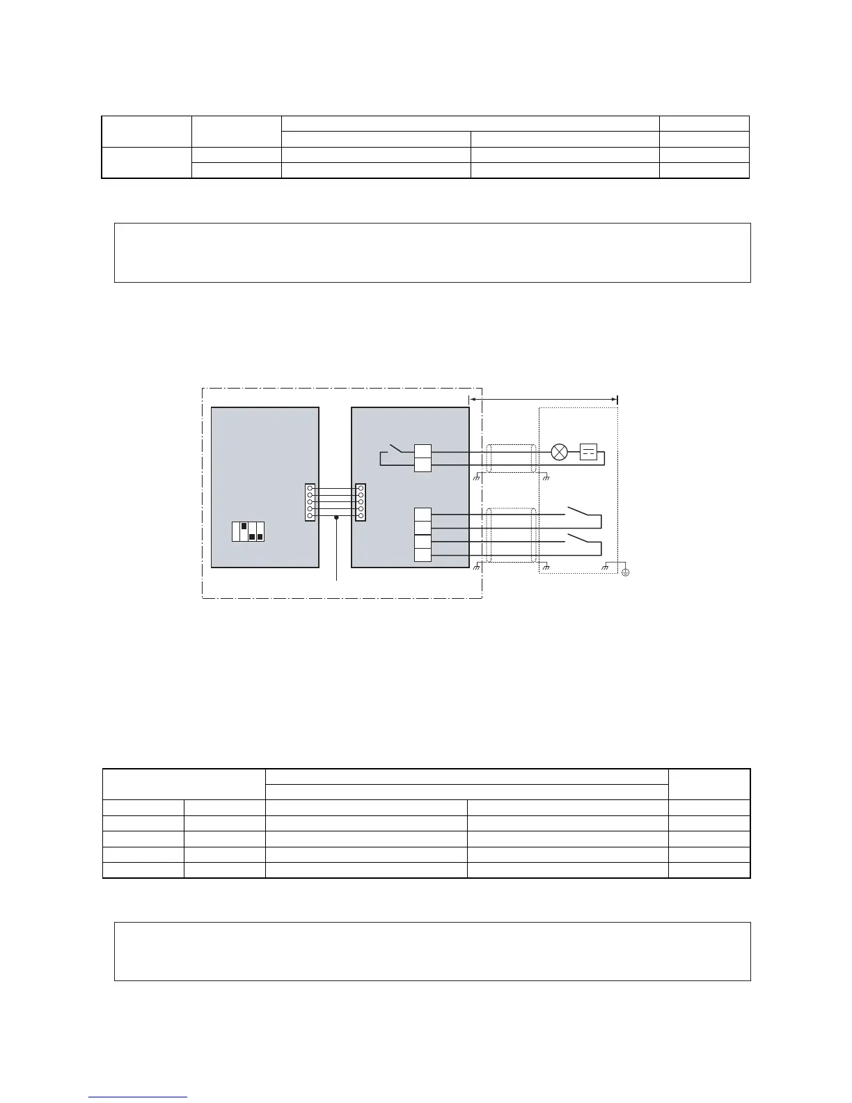
For SW1 and SW2, be sure to provide
no-voltage contacts for each terminal.
SW1 SW2 OFF ON L1
OFF OFF 100% (normal operation) 100% (normal operation) OFF
ON OFF 80% (upper limit regulated) 85% (upper limit regulated) ON
OFF ON 60% (upper limit regulated) 75% (upper limit regulated) ON
ON ON 0% (forced stop) 60% (upper limit regulated) ON
I/F SW07 Bit 1
Peak capacity
External power peak-cut control
signals
Indication lamp
Note 1: Specifications of display relay contact
• The terminal for display output ([Operation] terminal) must satisfy the following electrical rating.
When connecting a conductive load (e.g. relay coil) to the display relay load, insert a surge killer CR (for an AC
power supply) or a diode for preventing back electromotive force (for a DC power supply) on the bypass circuit.
The optional P.C. board should be connected to the header outdoor unit (U1).
7-3-2. Power peak-cut Control (Extended) : TCB-PCDM4UL
Operation
An external power peak-cut control signal limits the peak capacity of the outdoor unit.
L1: Power peak-cut control indication lamp
SW1: Power peak-cut control ON switch*1
SW2: Power peak-cut control OFF switch*1
*1 The inputs of SW1 and SW2 can be either pulse (100 msec or wider) or step signals.
* Be sure to provide a contact for each terminal.
Extended power peak-cut control settings
Specifications of display relay contact
Note 1: Specifications of display relay contact
• The terminal for display output ([Operation] terminal) must satisfy the following electrical rating.
When connecting a conductive load (e.g. relay coil) to the display relay load, insert a surge killer CR (for an AC
power supply) or a diode for preventing back electromotive force (for a DC power supply) on the bypass circuit.
The optional P.C. board should be connected to the header outdoor unit (U1).
 Loading...