chapter 3000
page 3
1,2 - 2,0 t A.C.
SERVICE MANUAL
Electric
036-0410-07
BRAKE SYSTEM
The brake system uses the
AGIP BRAKE FLUID DOT 4
This is used only in the brake system and not in the reduction gear.
The brake oil tank is located in the front side of the machine below the
dashboard. After pressing the brake pedal the oil pressure moves the
brake cylinder, which, acting on the brakes, creates the brake effect.
Warning light (3) on the dashboard
When the liquid in the brake tank is too low, the warning light comes
ON. If the warning light (3) comes ON, check that there are no
leaks in the system.
BRAKE OIL TANK
SERVICE BRAKE
Oil-bath brakes are inside the reduction gear box and use
the same oil.
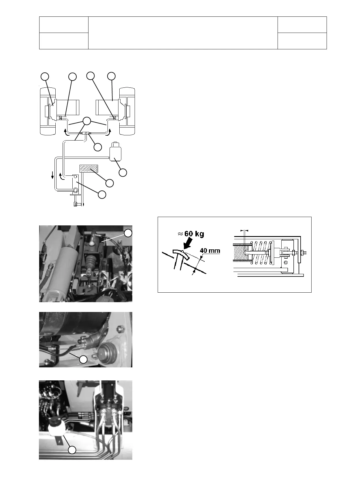
SERVICE BRAKE SYSTEM
DIAGRAM
M)Reduction gears and braking unit
N) Parking brake command
O) Bleeding screw
P) Electric drive motor
Q) Distribution block
R) Tank
S) Service brake pedal
T) Command pump
U) Brake pipes
M
Q
P
O
N
U
T
S
BRAKE PIPES
BRAKE PEDAL
R
SERVICE BRAKE CONTROL
Every 1000 hours
- check that the braking system liquid level in the tank has not dropped;
if it has, check the system.
- control functioning of the service brake pedal and the parking brake
pedal or lever , they must be smooth and with no jamming;
Every 2000 hours
- change the braking system liquid.
Every 5000 hours
- replace brake hoses.
Clearance of the brake pedal in neutral position
approximately 1 mm
R
U
T
 Loading...
