7 . ACCESSORIES AND OPTIONS
7.76
Challenger MT500B EU
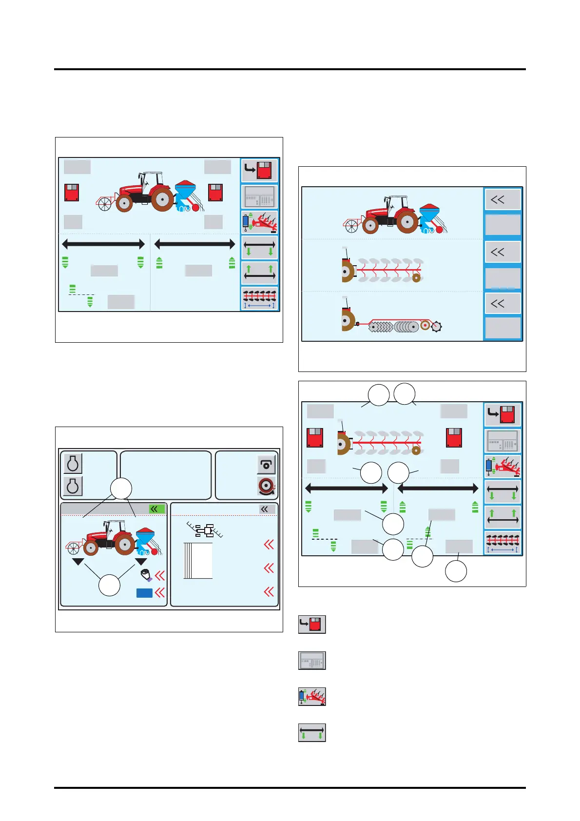
Displaying parameters:
During work either the Settings window (Fig. 179), or the
Work window (Fig. 180) can be displayed.
Description (Fig. 179):
As the front and rear linkage positions change, the corre-
sponding height values change.
The values in the grey boxes are memorised and fixed.
Description (Fig. 180):
To display this window, press the key «
2
when the win-
dow (Fig. 179) is open.
Left-hand part of the window:
The linkage position values (30) are the active values.
The symbols under the linkages (31) indicate their control
status.
Right-hand part of the window:
See section 7.8.5 (POINTS menu).
7.13.3 - REAR DUAL CTRL
NOTE: In this section, explanations shall be illustrated
by a semi-mounted plough example.
When the window (Fig. 181) is open, press the key
«
3
. The
window (Fig. 182) is displayed.
Description:
1920
42.0
100%100%
0%
0%
77% 83%
6.0
6.0
6.0
6.0
15%
21% 32%
15%
Z3A-961-08-04-B
Fig. 179
m
m
m
m
A
B
1000
2000
790
5.3
10% M
5%
2
2000
21 % 32%
ON
0.0
0.0
Reset
1
Z3A-962-08-04-B
Fig. 180
FRONT DUAL CTRL
POINTS
m
m
RPM
KPH
30
31
Memorises high and low implement positions
Displays the REAR DUAL CTRL menu in the
WORK application
Opens the linkage calibration menu
Authorises furrow start setting
Z3A-817-08-04
1
5
3
?
?
?
Fig. 181
100%100%
100%
0%
0%
0%
100%
0%
100%
100%
6.0
6.0
100%
100%
6.0
6.0
1920
42.0
Z3A-798-08-04-B
Fig. 182
m
m
m
m
32
36
34
37
38
39
33
36
1920
42.0
 Loading...