7 . ACCESSORIES AND OPTIONS
7.95
Challenger MT500B EU
7
Change hydraulic feed hoses in poor condition as a preven-
tive measure, even if there is no leak (danger of bursts dur-
ing use).
Breakdowns and accidents always cost more.
• Greasing: (see section 5.6).
7.16 - FRONT POWER TAKE-OFF
7.16.1 - Power level allowed
Unlike the power available to the rear PTO and the wheels,
the front PTO power must be limited.
- For SISU engines, half of the engine power can be used
for the front PTO.
- For 6-cylinder Perkins engines, 75 hp is the maximum
power allowed at the front PTO.
- For 4-cylinder Perkins engines, there is no restriction.
Do not use implements that require higher power levels
than stated above. Instead, use the rear PTO for heavy
work (stationary grinders, etc.)
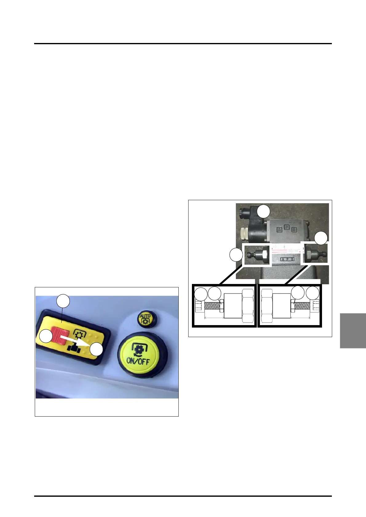
7.16.2 - Power Take-Off Control
The front PTO is controlled by the switch Ref.1 - Fig. 236
To engage PTO, slide the red safety slider in the direction
indicated by the arrow, while pressing the switch Ref. D in
order to unlock it.
Push as shown by Ref. E to stop PTO; in this position the
switch prevents it from disengaging accidentally.
IMPORTANT: When the PTO is stopped, the PTO brake
is engaged.
The cab control activates a solenoid valve placed close to
the front PTO unit; this valve controls the PTO clutch and
brake.
The pressure at the valve inlet is 17 bar, but the flow rates
for the clutch and brake can be adjusted separately (Fig.
237). Screw 1 allows the user to adjust the brake oil flow
rate; screw 2 that of the clutch.
1. Adjusting the brake:
Set screw 1 is preset with an opening of 9 mm.
If the engine is running and the clutch is released but
the PTO shaft rotates alone, braking power should be
increased by loosening screw 4 until the rotation
stops. Retighten locknut 5.
2. Adjusting the clutch:
Set screw 2 is preset with an opening of 13 mm,
which corresponds to the maximum oil flow rate.
If using implements of low inertia requiring low levels
of power, clutch progressivity can be increased by
tightening set screw 6.
IMPORTANT: If the screw is too tight, the torque to be
transmitted to the implement might exceed the torque
provided by the clutch; in this case excessive clutch
slippage will cause premature clutch wear. To avoid
this problem, loosen set screw 6 to reduce clutch pro-
gressivity and prevent clutch slippage.
• Maintenance
In addition to taking good care of equipment during use, it
should be maintained at regular intervals. This helps ensure
manufacture quality performance and reliability for a
number of years.
Regularly check the tightness of attachment screws, espe-
cially the first few times the linkage is used. Incorrect tight-
ening causes parts to move among themselves and
reduces the strength of the linkage.
Fig. 236
Z2-039
D
S
1
Fig. 237
3
1
4
5
6
13mm9mm
2
5
 Loading...