4 . MAINTENANCE AND ADJUSTMENTS
4.24
Challenger MT500B EU
4.13.1 - Attaching an implement from the driver’s
seat
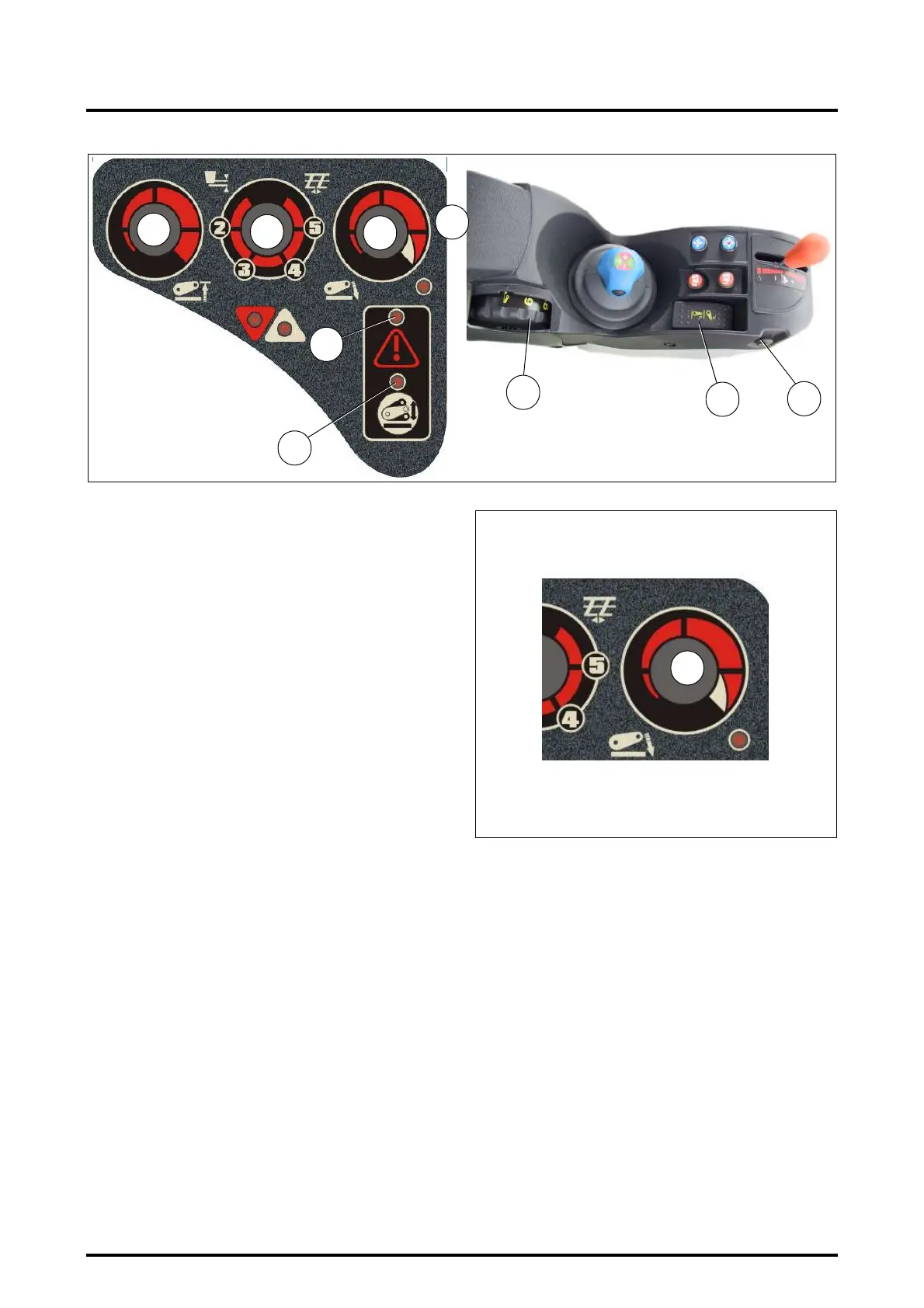
Start the engine. Indicator lights (I), (J) and (K) come on.
- ((K) and (J) light up for 0.5 second approximately.
- ((I) stays on until the console is activated.
- Adjust the control knobs.
- Move the function selector knob (B Fig. 42) clockwise to
minimum control position.
- Move the Lift / Lower selector switch (E) to the lift posi-
tion.
- Adjust the linkage height in turning the control knob (A).
- The Lift indicator light (H) comes on.
4.13.2 - Lowering
To lower the linkage, turn knob (A) clockwise. The lowering
indicator light (G) will come on.
In automatic mode, lowering speed is governed by two pa-
rameters: the weight of the implement and ground speed.
The indicator light (K) comes on when this mode is select-
ed.
Legend Fig. 43:
1. Lowering lock position
2. Lowering speed slow
3. Lowering speed fast
4. Automatic mode
4.13.3 - Lifting
To lift the linkage turn the knob (A) anti-clockwise.
The Lift indicator light (H) comes on.
4.13.4 - Depth control
Knob (A) in position 1 (min.) to 7 (max.) determines the
depth of work.
In position 8 and 9 the linkage is in floating mode.
Z2-478-05-03
L
A
E
Fig. 42
D
C
K
Z2-476-05-03
I
J
B
D
1
2
3
Fig. 43
Z2-479-05-03
4
 Loading...