4 . MAINTENANCE AND ADJUSTMENTS
4.26
Challenger MT500B EU
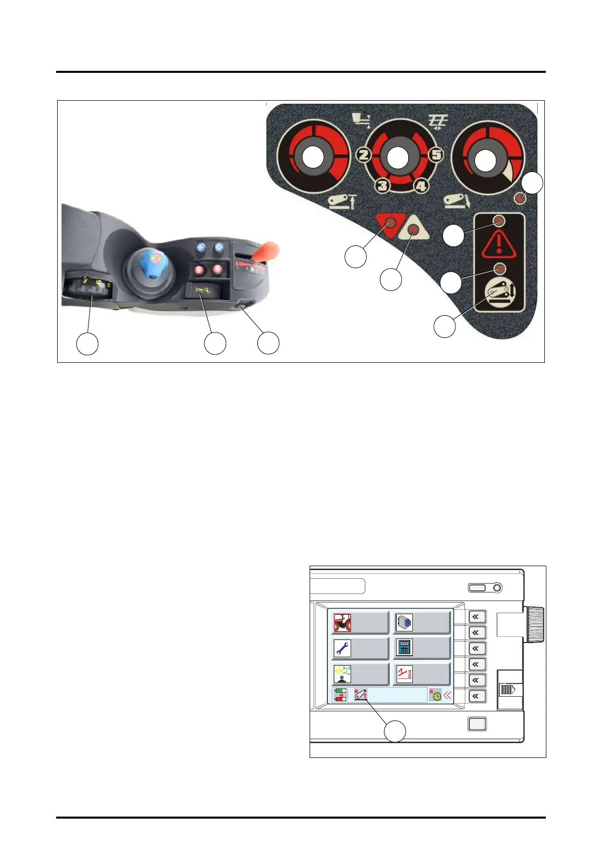
4.13.6 - Transport
- Select the minimum position with the knob (B, Fig. 46).
- Adjust the maximum linkage height according to the
transport implement using the height setting knob (C).
Start from minimum position.
Move the knob (D) to position 1 (padlock).
4.13.7 - Activate transport control system
- The system operates automatically when button (F) is
pressed; indicator light J comes on.
- To deactivate this function, button (F) must be pressed.
4.13.8 - Quick soil engagement
- Move the selector switch (E) to Lowering position,
press and hold button (L) to trigger quick soil engage-
ment.
- Release as soon as the plough is engaged into the soil.
4.13.9 - Use when working
- Adjust the maximum high position using knob (C).
- Using knob (D), adjust a maximum linkage lowering
speed.
- Choose the implement control mode (Draft, Position or
Intermix Control), according to the implement, the
ground conditions and the type of work, by activating
the control selector knob (B).
- Adjust the working depth using knob (A).
- The Lift and Lower indicator lights (H) and (G) allow to
display the work being carried out.
4.13.10 - Operation at headlands
Put the Lift / Lower selector switch (E) into the Lift position.
The linkage will rise to the preselected maximum lift posi-
tion (C).
In order to resume work, put the Lift/Lower selector switch
(E) into “Lower”. The depth settings previously made will
be repeated.
NOTE: A safety cut-out puts the linkage system out of
operation when the ignition is switched off, the engine
stopped (ignition switched off), or external controls are
used.
The object of this device is to avoid any accidental move-
ment of the linkage if settings on the console have been al-
tered, while the tractor is stationary.
To reactivate the linkage, move the switch (E) to the inter-
mediate position, then to the lift position. Linkage is then
brought back into operation and the padlock (N Fig. 47) in
the DATATRONIC 3 window disappears, if this latter has
been installed.
Z2-478-05-03
L
A
E
Fig. 46
B
D
C
J
F
H
I
Z2-476-05-03
G
K
1
2
3
4
5
6
ESC
Z3A-782-08-04
Fig. 47
N
WORK
SETTINGS
HEADLAND DUAL CTRL
MEMORIES
EHS VALVES
 Loading...