7 . ACCESSORIES AND OPTIONS
7.28
Challenger MT500B EU
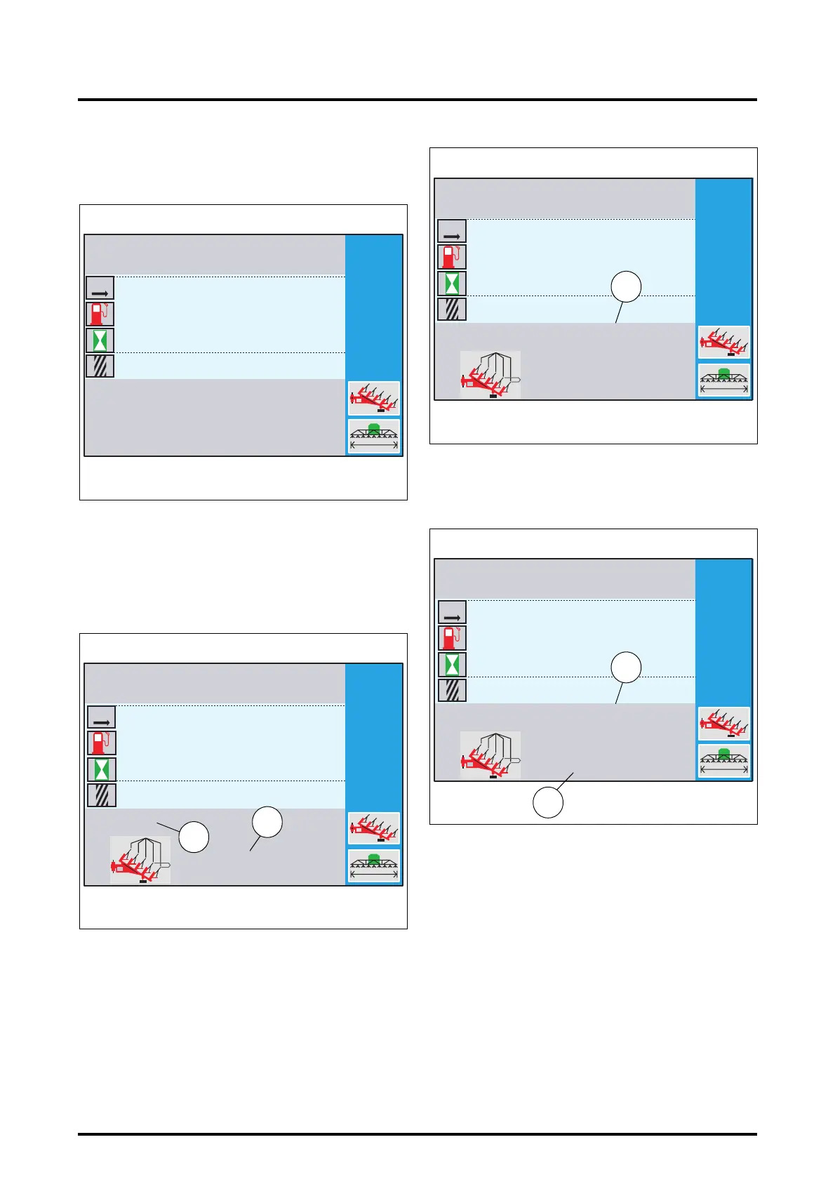
7.8.4 - Setting any implement width
• When the window (Fig. 17) is open, press the key
«
4.
. A
new window is displayed (Fig. 18).
• If a plough is used, press the key
«
5
. If any implement is
used, press the key
«
6.
.
Setting a plough width:
• Press the key
«
5
when the window (Fig. 18) is open.
The settings window (Fig. 19) is displayed.
20. Number of plough bodies
21. Distance in inches between bodies
As soon as the window opens, the number of bodies is dis-
played in red on colour screens and in reverse video on b/
w screens. This value can therefore be set.
• Set the number of plough bodies (20) by rotating the encoder
(1 to 22 bodies). As soon as the encoder is rotated, the work-
ing width is displayed according to the selected distance in
inches between the bodies (22 Fig. 20).
• Validate this number by pressing the encoder. The
number of bodies is now displayed in black and the
width in inches is displayed in red on colour screens and
in reverse video on b/w screens (23 Fig. 21).
• Set the width in inches by rotating the encoder (from 8
to 30 inches). The working width (22) varies according to
the value displayed.
• Validate by pressing the encoder. The window (Fig. 22)
is displayed.
1
4.5
0
0 000
0:00
0.0
0
0.0
0:00
Z3A-908-08-04-B
Fig. 18
PLOUGH
KM
M
M
L
HA
H
1
5
14''
0
0 000
0:00
0.0
0
0.0
0:00
12/18
5.48
Z3A-909-08-04-B
Fig. 19
PLOUGH
20
21
KM
M
M
L
HA
H
1
14''
4.2612
4.5
0
0 000
0:00
0.0
0
0.0
0:00
Z3A-910-08-04-B
Fig. 20
PLOUGH
M
22
KM
M
M
L
HA
H
1
18''
5.4812
4.5
0
0 000
0:00
0.0
0
0.0
0:00
Z3A-911-08-04-B
Fig. 21
PLOUGH
M
23
KM
M
M
L
HA
H
22
 Loading...