4 . MAINTENANCE AND ADJUSTMENTS
4.29
Challenger MT500B EU
4
Setting Joystick parameters with Datatronic 2
For a correct use of Datatronic 2, refer to chapter 7.
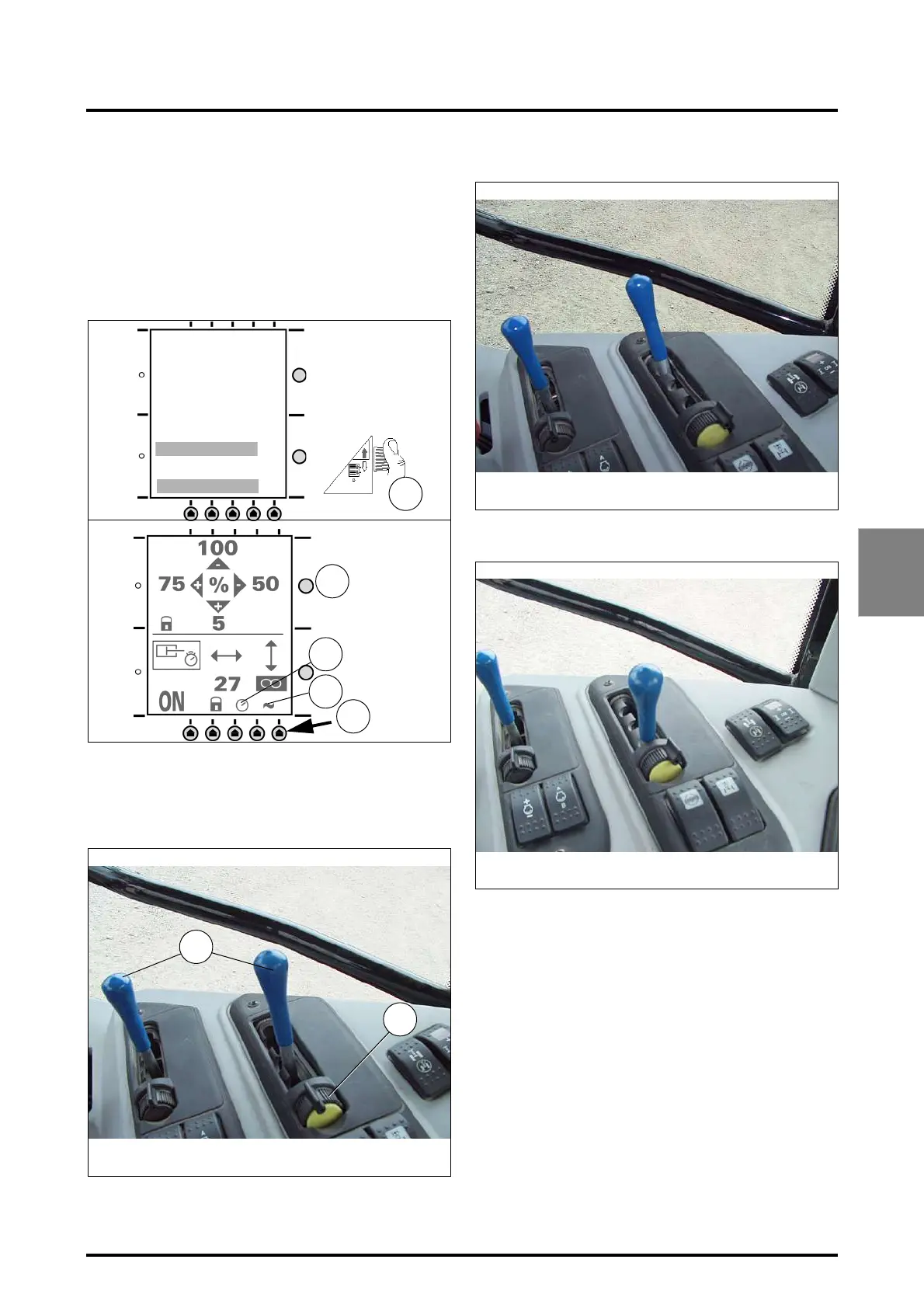
Description of the display (Fig. 53):
Ref. 5. Selection keys for the 2 half-screens.
Ref. 6. Selecting functions
Ref. 7. Stored data modification key.
Ref. 8. Time delay
Ref. 9. Floating position.
4.15.6 - Using the control levers (Fig. 54)
Each spool valve controlled by a lever (A), can be blocked
in various positions by actuating the lock (D):
• Neutral position (Fig. 54)
• Ram rod extraction position (for example) (Fig. 55)
• Ram rod retraction position (for example) (Fig. 56)
• Floating position (Fig. 57)
To activate the floating position, push the lever to its maxi-
mum position (E), then release it. The lever returns to its in-
itial position, while the spool valve is in floating position.
To deactivate the floating position, move the lever to any
position. The spool valve switches to neutral position.
Fig. 53
5
6
8
9
7
Preselection
Adjustment
TRAIL ADJ.
DUAL
FRONT CTRL
REAR CTRL
REAR ADJ
FRONT ADJ
-JOYSTICK-
MAX FLOW
KICK OUT
Fig. 54
Z3A-821-08-04
D
A
Fig. 55
Z3A-822-08-04
Fig. 56
Z3A-823-08-04
 Loading...