7 . ACCESSORIES AND OPTIONS
7.29
Challenger MT500B EU
7
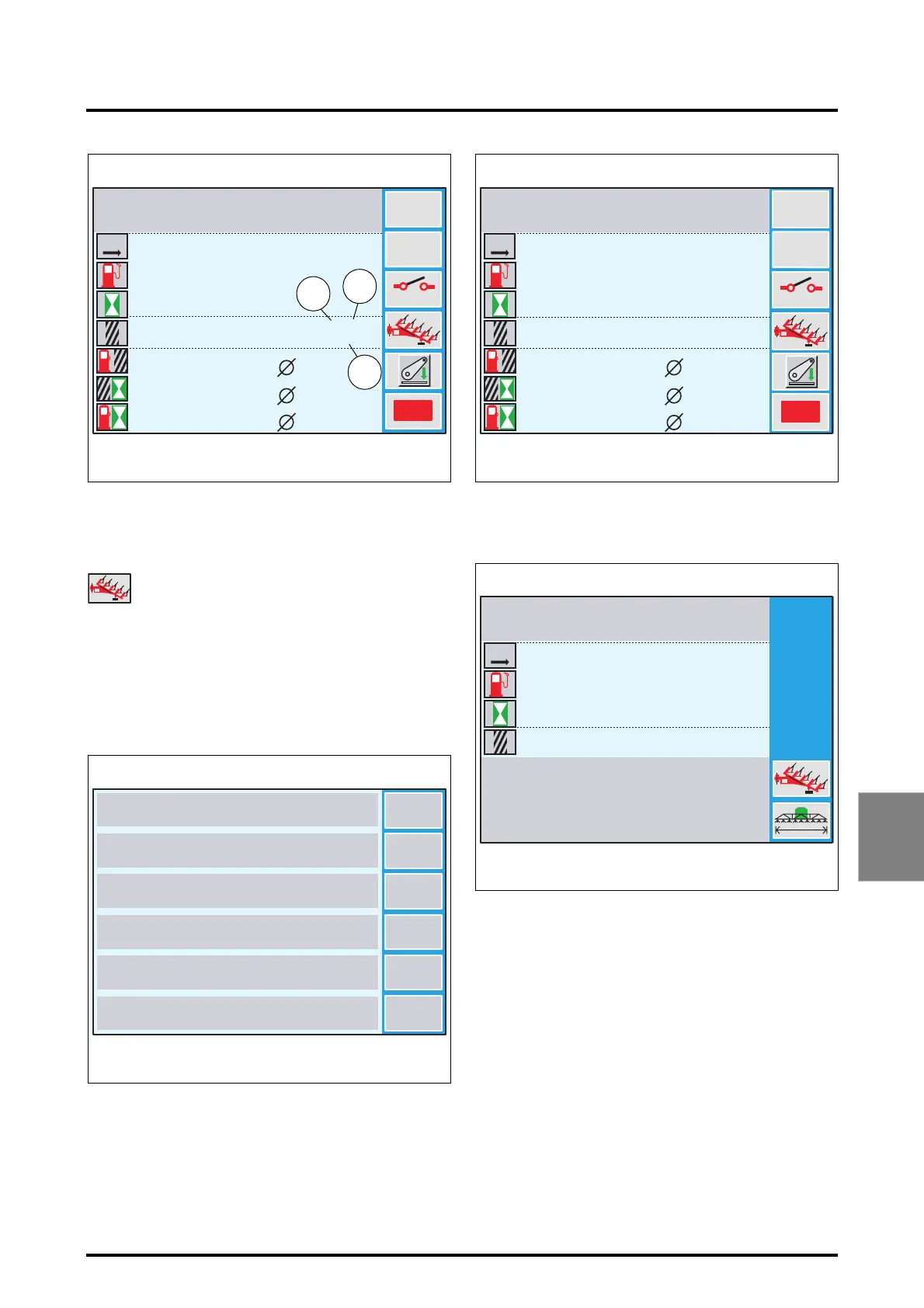
24. Number of plough bodies
25. Distance between bodies
26. Working width
Setting an implement width:
• Select an implement to configure in the window (Fig.
23). Example: DISC TILLER by pressing the key «
3
. This
implement window (Fig. 24) is displayed.
• Press the key
«
4
, whatever the icon displayed facing
this key (plough or sprayer). The settings window (Fig.
25) is displayed.
• Press the key
«
6
to display the settings window (Fig.
26). The width is displayed in red on colour screens (27)
or in reverse video on b/w screens.
Icon representing the plough
1
ABC...
OFF
=
=
=
Reset
0
0
0.0
0.0
0 000
0:00
0.0
0.0
0.0
0.0
0.0
0
0.0
0:00
12/18
5.48
Z3A-912-08-04-B
Fig. 22
PLOUGH
25
26
KM
M
24
L/HA
HA/H
L/H
M
L
HA
H
1
5
4
3
2
6
DUAL CTRL AR
DUAL CTRL AV
Z3A-894-08-04-B
Fig. 23
PLOUGH
SELF LOADING TRAILER
DISC TILLER
SUBSOILER
SPREADER
ROTARY HARROW
3
ABC...
OFF
=
=
=
Reset
0
0
0.0
0.0
0 000
0:00
0.0
0.0
0.0
0.0
0.0
0
0.0
0:00
12/18
5.48
Z3A-923-08-04-B
Fig. 24
DISC TILLER
KM
M
L/HA
HA/H
L/H
M
L
HA
H
3
0
0 000
0.0
0.0
0
0.0
0:00
12/18
5.48
Z3A-924-08-04-B
Fig. 25
DISC TILLER
KM
M
M
L
HA
H
 Loading...