CHAPTER
1-1
Cisco 7600 Series Router Module Guide
OL-9392-05
1
Modules Overview
This chapter provides important information about the Cisco 7600 series routers modules. This chapter
contains these sections:
• LEDs, page 1-1
• Port Addresses, page 1-2
• Hot Swapping Modules, page 1-4
• Power Management and Environmental Monitoring, page 1-4
• Limiting Connection Distances, page 1-4
• Port Densities, page 1-6
• Gigabit Interface Converters, page 1-7
• Software Requirements, page 1-13
This book does not contain instructions for installing the router chassis or for installing modules in the
router chassis. For information on installing the router chassis, refer to the
Cisco 7600 Series Router
Installation Guide. For information on installing modules in a router chassis, refer to the Cisco 7600
Series Router Module Installation Guide.
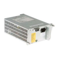
LEDs
The LEDs on the router module front panel indicate the status of the module. Table 1-1 lists the LEDs
and their function.
Ta b l e 1-1 Router Module LEDs
LED Color/State Description
STATUS Green All diagnostics pass. The module is operational (normal initialization sequence).
Orange The module is booting or running diagnostics (normal initialization sequence).
Make sure the module is fully seated in its slot and that the ejector levers are completely
closed.
An overtemperature condition has occurred. (A minor temperature threshold has been
exceeded during environmental monitoring.)

 Loading...