3-2
Cisco 7600 Series Router Module Guide
OL-9392-05
Chapter 3 ATM Modules
1-Port OC-12 ATM Module (WS-X6101-OC12-SMF)
Figure 3-1 ATM OC-12 Module (MMF) (WS-X6101-OC12-MMF)
The front panel LEDs are described in Table 3-1 on page 3-3.
1-Port OC-12 ATM Module (WS-X6101-OC12-SMF)
The 1-port ATM module (WS-X6101-OC12-SMF) provides one direct connection and one standby
connection between the ATM network and the switch using two single-mode, SC, fiber-optic connectors.
(See
Figure 3-2.)
The CONSOLE PORT allows you to access the switch either locally (with a console terminal) or
remotely (with a modem). The CONSOLE PORT is an EIA/TIA-232 asynchronous, serial connection
with hardware flow control and an RJ-45 connector.
The CONSOLE PORT MODE switch allows you to attach either a terminal or a modem to the console
port.
Note Use a ballpoint pen tip or other small, pointed object to access the CONSOLE PORT MODE switch.
Use the CONSOLE PORT MODE switch as follows:
• Mode 1—Switch in the in position (factory default). Use this mode to connect a terminal to the
CONSOLE PORT using a console cable and a DTE adapter. You can also use this mode to connect
a modem to the console port.
• Mode 2—Switch in the out position. Use this mode to connect a terminal to the CONSOLE PORT
using the Catalyst
5000 family Supervisor Engine III console cable (not provided).
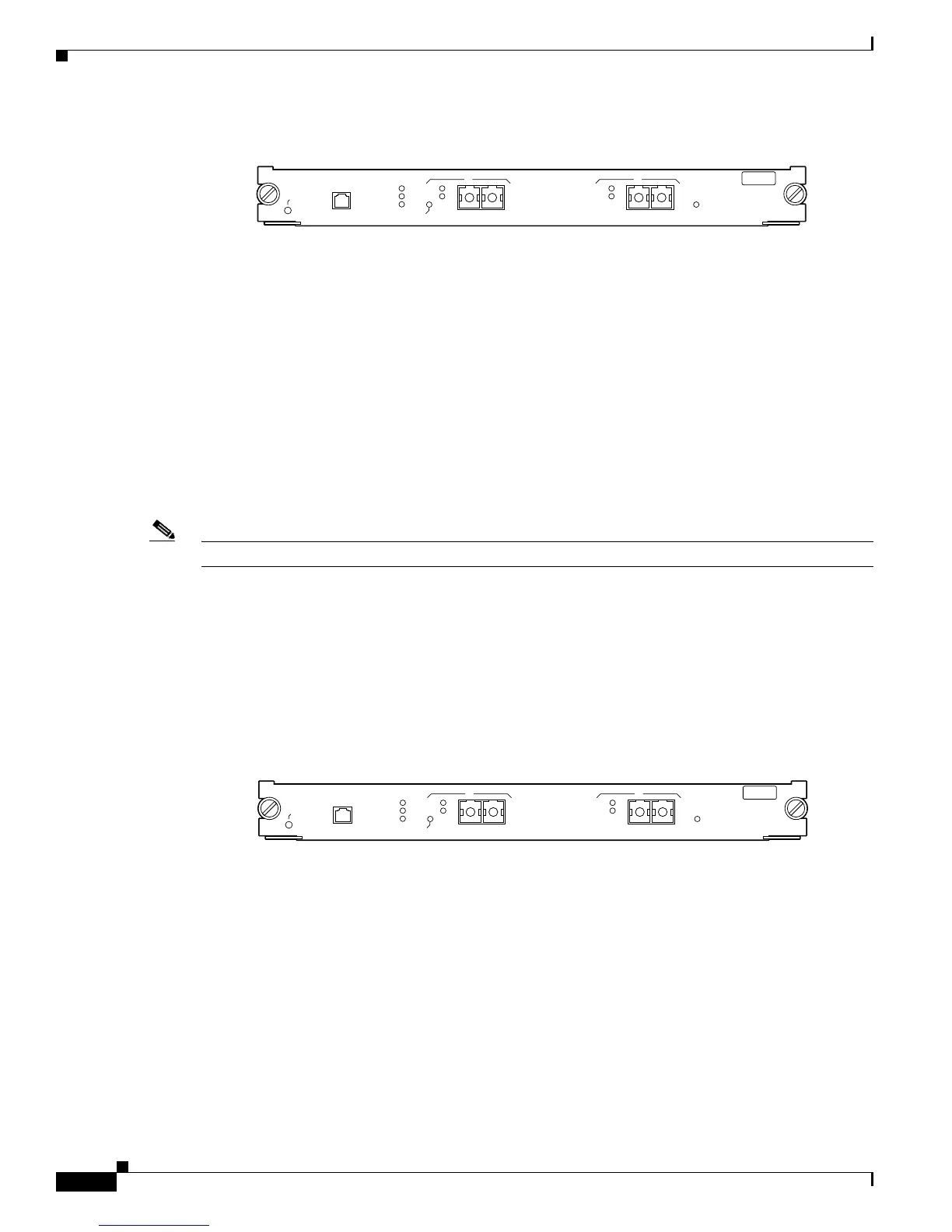
Figure 3-2 ATM OC-12 Module (SMF) (WS-X6101-OC12-SMF)
The front panel LEDs are described in Table 3-1 on page 3-3.
MULTIMODE OC-12 ATM
WS-X6101-OC12-MMF
CONSOLE PORT TX
RX
ACTIVE
SIGNAL
LINK
CONSOLE
PORT
MODE
STATUS
26949
UNI-622MM
A
ACTIVE
SIGNAL
UNI-622MM
B
SINGLE MODE OC-12 ATM
WS-X6101-OC12-SMF
CONSOLE PORT TX
RX
ACTIVE
SIGNAL
LINK
CONSOLE
PORT
MODE
STATUS
26951
UNI-622MM
A
ACTIVE
SIGNAL
UNI-622MM
B

 Loading...