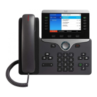
For cables that terminate outside of the bracket, use the cable-access openings in the bottom of the bracket to
position the power cord and any other cable that does not terminate in the wall behind the bracket. The phone
and wall bracket openings together form circular openings with room for one cable per opening.
Step 5 Proceed to Adjust the Handset Rest, on page 136.
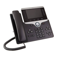
Remove the Phone and Key Expansion Module from the Non-Lockable Wall
Mount
The wall bracket has two tabs that lock the kit together. Use the following illustration to locate the tabs.
Cisco IP Phone 8800 Series Multiplatform Phones Administration Guide
135
Hardware and Accessory Installation
Remove the Phone and Key Expansion Module from the Non-Lockable Wall Mount
 Loading...