2-4
Catalyst 3650 Switch Hardware Installation Guide
OL-29734-01
Appendix 2 Connector and Cable Specifications
Connector Specifications
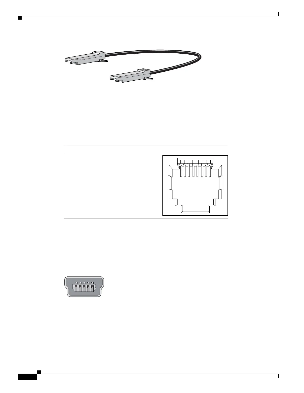
Figure 2-7 SFP Module Patch Cable
10/100/1000 Ethernet Management Port
The 10/100/1000 Ethernet management port uses RJ-45 connectors with Ethernet pinouts. Figure 2-8
shows the pinouts.
Figure 2-8 10/100/1000 Port Pinouts
Console Port
The switch has two console ports: a USB 5-pin mini-Type B port on the front panel (see Figure 2-9) and
an RJ-45 console port on the rear panel.
Figure 2-9 USB Mini-Type B Port
The USB console port uses a USB Type A to 5-pin mini-Type B cable, shown in Figure 2-10. The USB
Type A-to-USB mini-Type B cable is not supplied. You can order an accessory kit (part
number 800-33434) that contains this cable.
60915
2 3145678Pin Label
1
2
3
4
5
6
7
8
TP0+
TP0-
TP1+
TP2+
TP2-
TP1-
TP3+
TP3-
345492
 Loading...