1-16
Catalyst 3650 Switch Hardware Installation Guide
OL-29734-01
Chapter 1 Product Overview
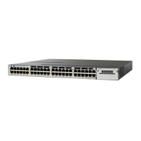
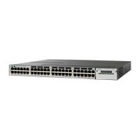
Front Panel
100M/1G/2.5G/5G/10G Ethernet Ports
The 100M/1G/2.5G/5G/10G Ethernet ports use RJ45 connectors with Ethernet pinouts. These ports do
not support 10 Mbps speed. The 100 Mbps and 1 Gbps traffic requires Category 5/5e/6 unshielded
twisted pair (UTP) cable, with a maximum cable length of 100 m. The 2.5 Gbps traffic requires Category
5e/6/6a UTP cable, with a maximum cable length of 100 m. The 5 Gbps traffic requires Category 5e UTP
cable, with a maximum cable length of 70 m, and Category 6/6a UTP cable, with a maximum cable
length of 100 m. The 10G traffic requires Category 6 UTP cable, with a maximum cable length of 55 m,
and Category 6a UTP cable, with a maximum cable length of 100 m.
PoE+ and Cisco UPOE Ports
The PoE+ and Cisco UPOE ports use the same connectors, as described in the “10/100/1000 Ethernet
Ports” section on page 1-15.
These PoE+ ports provide:
• Support for IEEE 802.3af-compliant powered devices (up to 15.4 W PoE per port) and support for
IEEE 802.3at-compliant powered devices (up to 30 W PoE+ per port).
• Support for Cisco-enhanced PoE.
• Support for prestandard Cisco-powered devices.
• Configurable support for Cisco intelligent power management, including enhanced power
negotiation, power reservation, and per-port power policing.
The Cisco UPOE ports provide support for powered devices (up to 60 W per port).
Depending on the installed power supply modules, each port can deliver up to 60 W of Cisco UPOE. See
Table 1-15 on page 1-33 for the power supply matrix that defines the available PoE and PoE+, and Cisco
UPOE power per port.
Note • For information on 250-W AC power supply support on the PoE-capable switch models, refer to the
Cisco Catalyst 3650 Series Switches Release Notes at
http://www.cisco.com/c/en/us/support/switches/catalyst-3650-series-switches/products-release-not
es-list.html.
• The output of the PoE+ circuit has been evaluated as a Limited Power Source (LPS) according to
IEC 60950-1.
Management Ports
• Ethernet management port (see the “Ethernet Management Port” section on page 1-37)
• RJ-45 console port (EIA/TIA-232) (see the “RJ-45 Console Port” section on page 1-38)
• USB mini-Type B console port (5-pin connector)
You can connect the switch to a host such as a Windows workstation or a terminal server through the
Ethernet management port, the RJ-45 console port, or the USB console port (USB mini-Type B port).
The USB console port connection uses a USB Type A to 5-pin USB Mini-Type B cable. The USB
console interface speeds are the same as the RJ-45 console interface speeds.
 Loading...