1-18
Catalyst 3650 Switch Hardware Installation Guide
OL-29734-01
Chapter 1 Product Overview
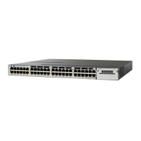
Front Panel
Cisco IOS software provides standard file system access to the flash device: read, write, erase, and copy,
as well as the ability to format the flash device with a FAT file system.
Uplink Ports
Depending upon the switch model, several uplink ports are available to connect to other devices:
• Four slots supporting only 1-Gigabit SFP modules
• Two slots (left side) supporting only 1-Gigabit SFP modules and two slots (right side) supporting
either 10-Gigabit SFP+ modules or 1-Gigabit SFP modules
• Two slots supporting either 1-Gigabit SFP modules or 10-Gigabit SFP+ modules
• Four slots supporting either 1-Gigabit SFP modules or 10-Gigabit SFP+ modules
• Eight slots supporting either 1-Gigabit SFP modules or 10-Gigabit SFP+ modules
• Two slots supporting 40-Gigabit QSFP+ modules
Note If you insert an SFP+ module in an SFP module slot, the SFP+ module slot does not operate, and the
switch logs an error message. SFP modules can operate in SFP+ module slots.
SFP, SFP+, and QSFP+ Modules
The SFP and SFP+ modules provide copper or fiber-optic connections to other devices. These
transceiver modules are field replaceable, and provide the uplink interfaces when installed in an SFP
module slot. The SFP modules have LC connectors for fiber-optic connections or RJ-45 connectors for
copper connections.
Use only Cisco SFP and SFP+ modules on the switch. For the latest information about supported
SFP/SFP+ modules, refer to Cisco Transceiver Modules Compatibility Matrix at:
http://www.cisco.com/en/US/products/hw/modules/ps5455/products_device_support_tables_list.html
The 40-Gigabit QSFP+ transceiver module is a hot-swappable, parallel fiber-optical module with four
independent optical transmit and receive channels. These channels can terminate in another 40-Gigabit
QSFP+ transceiver, or the channels can be broken out to four separate 10-Gigabit SFP+ transceivers.
For information on the 40-Gigabit QSFP+ module, refer to Cisco 40-Gigabit QSFP+ Transceiver
Modules Installation Note at:
http://www.cisco.com/c/en/us/td/docs/interfaces_modules/transceiver_modules/installation/note/OL_2
4862.html
LEDs
You can use the switch LEDs to monitor switch activity and its performance. Figure 1-8 shows the switch
LEDs and the Mode button that you use to select a port mode.
 Loading...