1-24
Catalyst 3650 Switch Hardware Installation Guide
OL-29734-01
Chapter 1 Product Overview
Front Panel
STACK LED
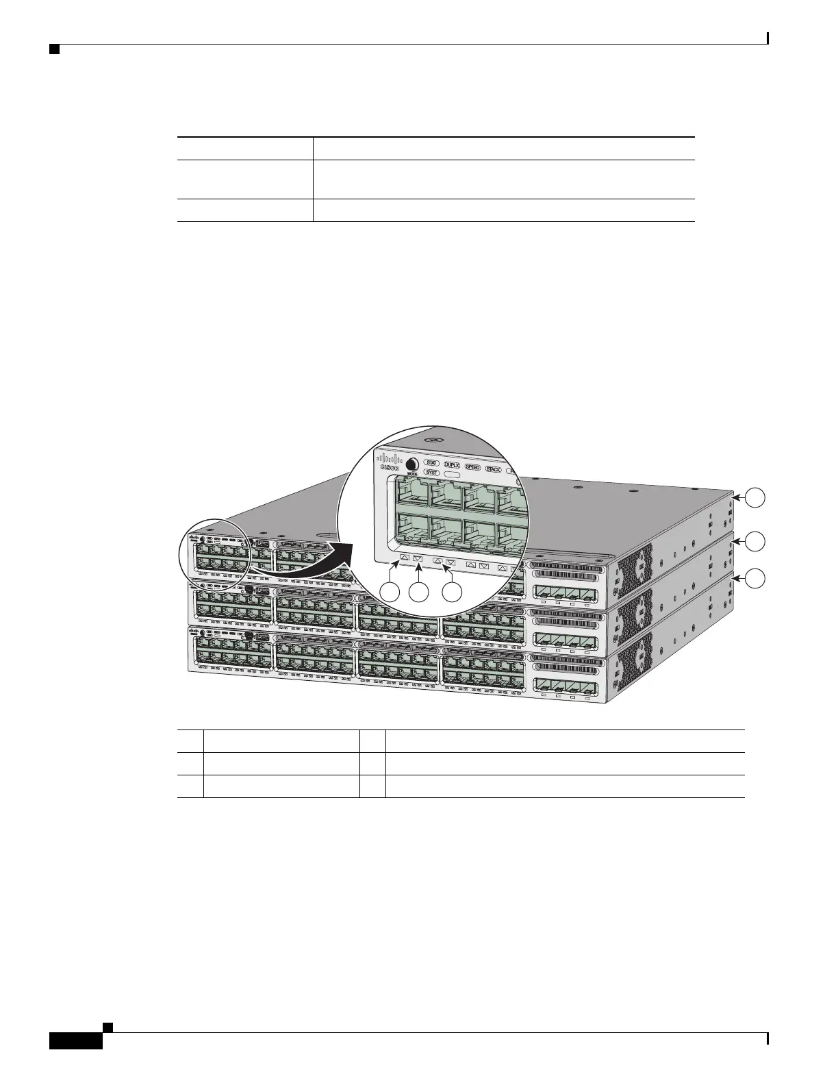
The STACK LED shows the sequence of member switches in a stack. Up to nine switches can be
members of a stack. The first nine port LEDs show the member number of a switch in a stack.
Figure 1-10 shows the LEDs on the first switch, which is stack member number 1. For example, if you
press the Mode button and select Stack, the LED for port 1 blinks green. The LEDs for port 2 and port
3 are solid green, as these represent the member numbers of other switches in the stack. The other port
LEDs are off because there are no more members in the stack.
Figure 1-10 STACK LED
When you select the STACK LED mode, the representative STACK LEDs are green when the StackWise
ports are up, and the representative STACK LEDs are amber when the ports are down.
RPS LED
The RPS LED is available only on the Catalyst 3650-24PDM and Catalyst 3650-48FQM switch models.
Amber An error occurred when the switch was selecting the active
switch, or another type of stack error occurred.
Slow blinking green Switch is in stack standby mode.
Table 1-6 ACTV LED (continued)
Color Description
1 Stack member 1 4 LED blinks green to show that this is switch 1 in the stack.
2 Stack member 2 5 LED is solid green to show that switch 2 is a stack member.
3 Stack member 3 6 LED is solid green to show that switch 3 is a stack member.
C
a
ta
ly
s
t 3
6
5
0
4
8
P
oE
+
2
X
1
0
G
C
a
ta
ly
s
t
3
6
5
0
4
8
P
oE
+
2
X
1
0
G
T
E
3
T
E
4
T
E
3
C
a
ta
ly
s
t
3
6
5
0
4
8
P
oE
+
2
X
1
0
G
T
E
4
T
E
3
T
E
4
347617
5
64
1
2
3
01X
13X
1
2X
24X
2
5X
36X
37X
4
8X
01X
13X
1
2X
24X
2
5X
36X
37X
4
8X
01X
13X
1
2X
24X
2
5X
4
8X
ACT
V
A
C
T
V
AC
T
V
Ca
t
a
l
y
s
t
3
6
5
0
4
8
P
oE
+
2
X
1
0
G
T
E
3
G
1
G
2
G
3
G
4
T
E
4
Ca
t
a
l
y
s
t
3
6
5
0
4
8
P
oE
+
2
X
1
0
G
T
E
3
G
1
G
2
G
3
G
4
T
E
4
C
a
tal
y
s
t
3
6
5
0
4
8
P
o
E
+
2
X
1
0
G
TE
3
G
1
G
2
G
3
G
4
T
E
4
 Loading...