4-13
Catalyst 3650 Switch Hardware Installation Guide
OL-29734-01
Chapter 4 Power Supply Installation
Finding the Power Supply Module Serial Number
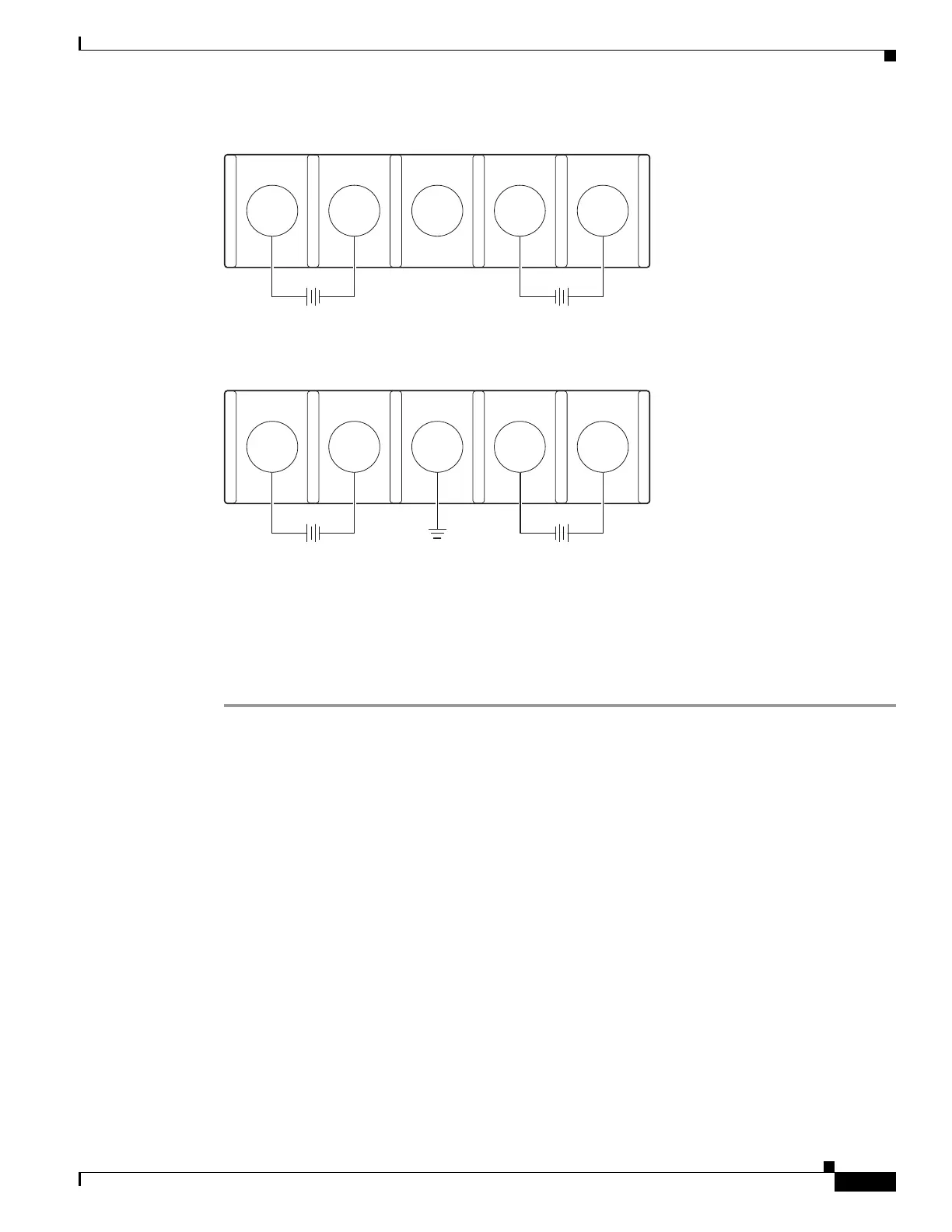
Figure 4-14 DC Source A Isolated from Source B with No Common Ground
Figure 4-15 DC Source A and Source B Connections with Common Ground
Step 4 Torque all the terminal block screws to 11 lbf-in.
Step 5 Replace the terminal block safety cover.
Step 6 Move the DC power source circuit-breakers to the ON position.
Step 7 Confirm that the power supply DC OK and PS OK LEDs are green. See Table 4-2 for a description of
the module LEDs.
Finding the Power Supply Module Serial Number
If you contact Cisco Technical Assistance regarding a power supply module, you should know the serial
number. See Figure 4-16 to Figure 4-20 to find the serial number.
253447
+
B-
B+
-
-
A+
A-
+
253446
+
B-
B+
-
-
A+
A-
+
 Loading...