• Attach an ESD-preventive wrist strap to your wrist and connect the other end to the grounding lug
connected to the chassis.
• You must use the supported SFP+ modules. The following SFP+ modules are supported on the Supervisor
PIC:
• SFP-10G-SR
• SFP-10G-LR
• SFP-10G-ER
• SFP-10G-ZR
• SFP-10G-LRM
Required Tools and Equipment
• ESD-preventive wrist strap
• SFP+ module
Step 1 Remove the SFP+ module from its protective packaging.
Do not remove the optical bore dust plugs.
Note
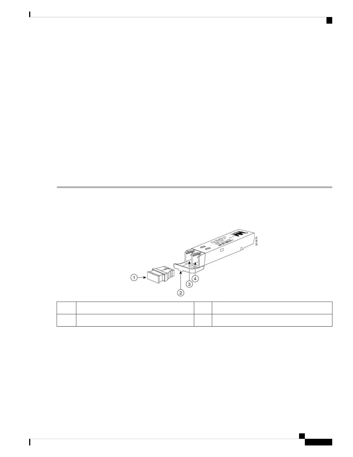
Figure 48: SFP+ Module with Dust Plugs
Transmit bore3Dust plug1
Receive bore4Bail clasp with clasp tab2
Step 2 Check the label on the SFP+ module to verify that you have the correct model for your network.
Step 3 Find the send (TX) and receive (RX) markings that identify the top side of the SFP+ module.
On some SFP modules, the TX and RX marking might be replaced by arrowheads pointing from the SFP+
module connector (transmit direction or TX) and towards the connector (receive direction or RX).
Note
Step 4 Align the SFP+ module in front of the socket opening.
Step 5 Carefully insert the SFP+ module into the socket until you feel the connector latch into place.
Cisco Converged Broadband Routers Hardware Installation Guide
93
Installing the Supervisor in the Cisco cBR Chassis
Installing the SFP+ Modules in the Supervisor PIC

 Loading...


