Connecting Power to the AC-Powered Cisco cBR Chassis
Before connecting AC Power to the AC FPEM, the chassis ground connection must always be made first and
disconnected last.
Warning
Only trained and qualified personnel should be allowed to install, replace, or service this equipment. Statement
1030
Warning
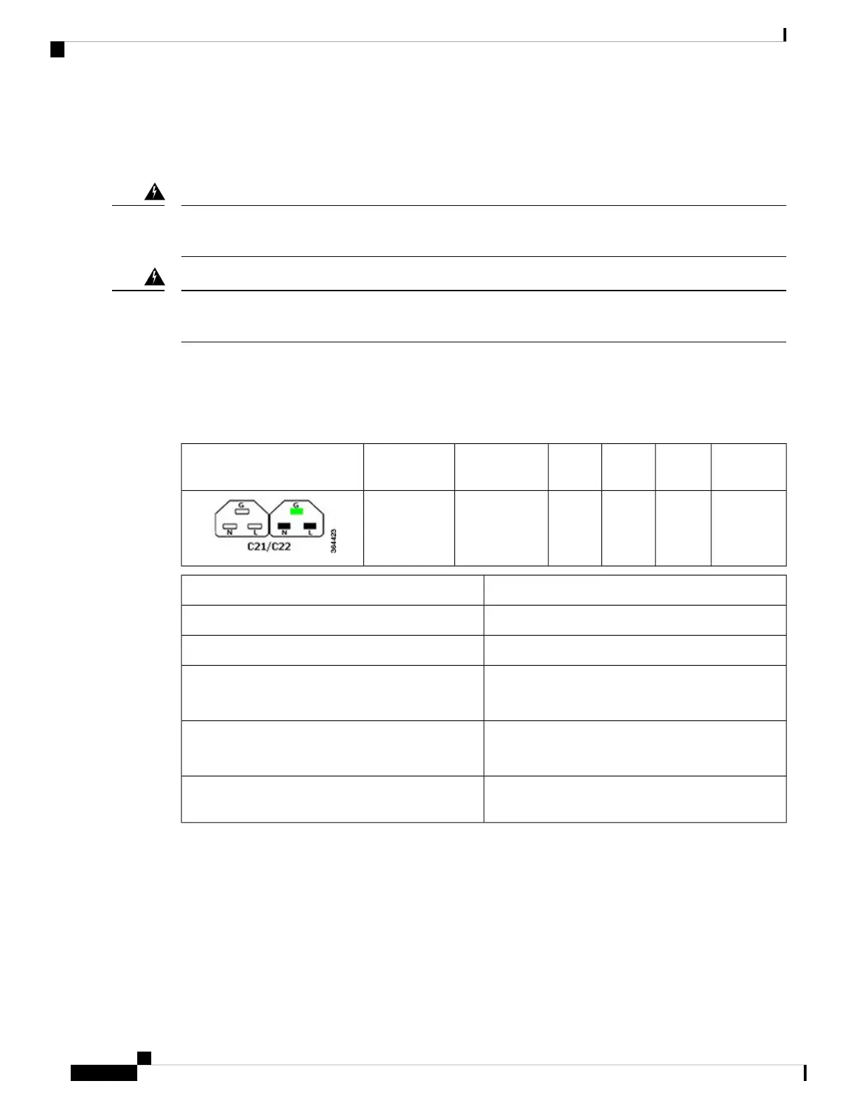
The AC FPEM has six input connectors. Each input connector corresponds to the AC Power Module installed
in the front of the chassis. They are IEC60320, C22 inlet connectors, which require facility power cords with
a C21 style connector. These are similar to a standard C19/C20 combination, but they have chamfers in the
upper corners, which are used to distinguish them as rated for 155C instead of the typical 70C used on the
C19/C20.
ConnectorInletPolesWiresRated Current
North America
Rated Current
International
Configuration Female/Male
C21C2223125/250 V
16 A
250 V
16 A
ValueDescription
Up to sixAC Power Modules per system
3400 VA facility inputTotal AC input power per AC Power Module
200-240 VAC nominal (range: 180 to 264 VAC)
220-240 VAC (UK)
Rated input voltage per AC Power Module
50/60 Hz nominal (range: 47 to 63 Hz)
50/60 Hz (UK)
Rated input line frequency
20 A North America; 16 A international; 13 A UK
(IEC60320 C22 connector on the chassis input side)
Source AC service requirement
Before you begin
• Attach the Chassis Ground Connection.
• Install the AC Power Cassette Module.
• Install the FPEM.
• Install the AC Power Modules.
Cisco Converged Broadband Routers Hardware Installation Guide
84
Installing the Power System in the Cisco cBR Chassis
Connecting Power to the AC-Powered Cisco cBR Chassis

 Loading...


