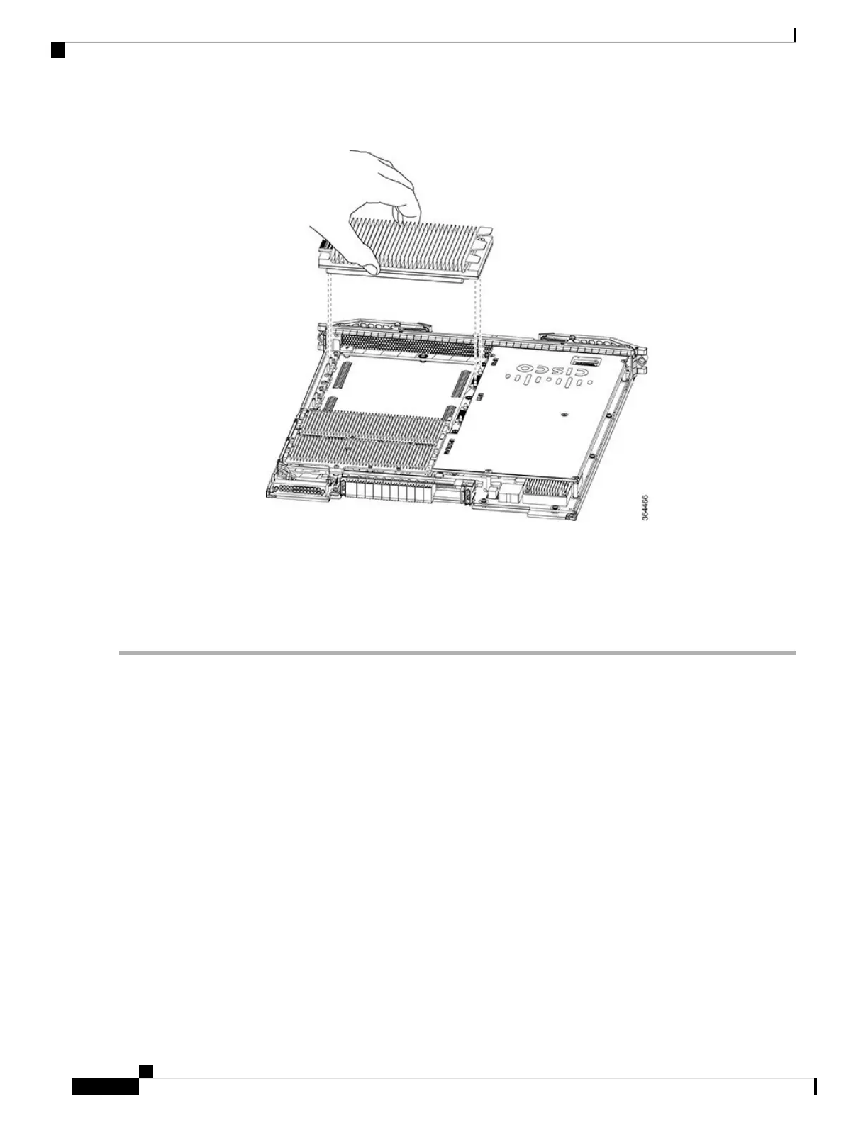
Figure 152: Grasp the Downstream PHY module
Step 2 Align the front and rear guide holes of Downstream PHY module with the front and rear guide pins on the line card.
Step 3 Gently lower the Downstream PHY module on to the guide pins of the line card.
Step 4 Tighten the three retaining screws using a T10 Torx-blade torque screwdriver.
Use a torque of 8 lb-inch (0.90 Nm) to tighten the screws.
Caution
What to do next
• Install the Interface line card.
• After the Interface line card is installed and reloading it, verify that the downstream PHY module is
upgraded from downstream D3.0 to downstream D3.1 module using the show inventory command. For
more details on the verification, refer to Verifying the Downstream PHY Module Upgrade.
Removing the Upstream PHY Module in the Interface Line Card
The Upstream PHY module is removed for replacement or upgrade.
Before you begin
Prerequisites
• Attach an ESD-preventive wrist strap to your wrist and connect its end to the grounding lug that is
connected to the chassis.
Cisco Converged Broadband Routers Hardware Installation Guide
232
Maintaining the PHY Modules in the Cisco cBR Chassis
Removing the Upstream PHY Module in the Interface Line Card

 Loading...


