Required Tools and Equipment
• AC power cord
• #2 Phillips torque screwdriver
Step 1 Ensure that the power switch on the AC FPEM is in off (down) position.
Step 2 Connect the AC power cord to the receptacle on the AC FPEM.
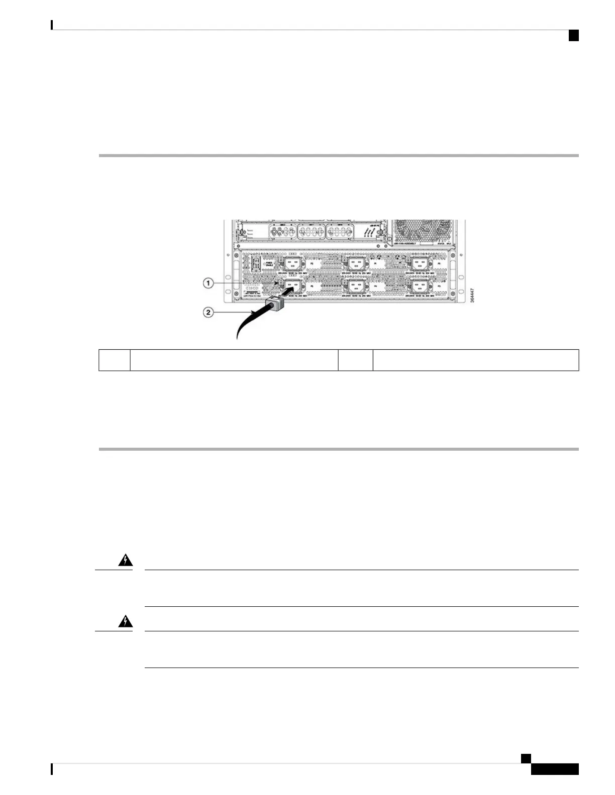
Figure 43: Connecting AC Power Cord to the AC FPEM
AC power cord2Screw on the cable retaining bracket1
Step 3 Tighten the Phillips-head screw on the cable retaining bracket using a #2 Phillips torque screwdriver with a torque of
8-10 in-lb (0.90-1.13Nm).
Step 4 Connect the other end of the AC power cord to the AC source receptacle.
Step 5 Repeat Step 2, on page 85 to Step 4, on page 85 for all power connections.
What to do next
If all the interfaces and other cables are connected, power up the Cisco cBR chassis.
Connecting Power to the DC-Powered Cisco cBR Chassis
The terminal block covers are an integral part of the safety design of the product. Do not operate the unit
without the covers installed. Statement 1077
Warning
Before connecting DC Power to the DC FPEM, the ground connection must always be made first and
disconnected last.
Warning
Cisco Converged Broadband Routers Hardware Installation Guide
85
Installing the Power System in the Cisco cBR Chassis
Connecting Power to the DC-Powered Cisco cBR Chassis

 Loading...


