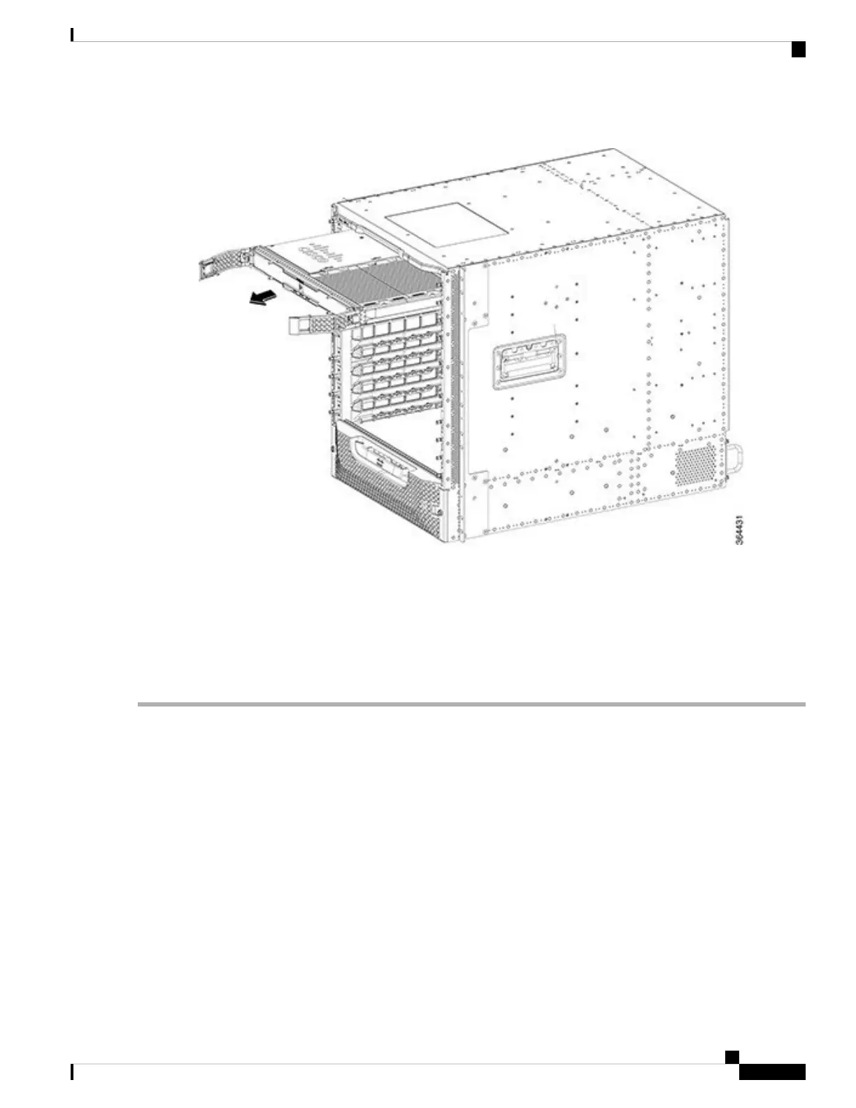
Figure 140: Removing the Interface Card from the Slot
Step 4 Grasp the faceplate of the card with one hand and place your other hand under the card to support its weight, and remove
the card from its slot.
Step 5 Place the removed card in an antistatic bag.
If a line card blank is removed, it need not be placed in an antistatic bag.
Note
Close the spring-loaded ejectors before placing it in the anti-static bag.
Note
What to do next
• Replace the Interface Line Card or install a line card blank (as required).
Removing the UCH.8 Connectors from the RF PIC
Three UCH.8 connectors are connected to the RF Through PIC. To remove a PIC, the UCH.8 connectors
connected to the PIC must be removed first. This procedure is used only for RF Through PICs. The following
steps describe how to remove one UCH.8 connector. Repeat the procedure to remove all the three UCH.8
connectors.
Before you begin
• Attach an ESD-preventive wrist strap to your wrist and connect the other end to the grounding lug
connected to the chassis.
Cisco Converged Broadband Routers Hardware Installation Guide
217
Maintaining the Interface Cards in the Cisco cBR Chassis
Removing the UCH.8 Connectors from the RF PIC

 Loading...


