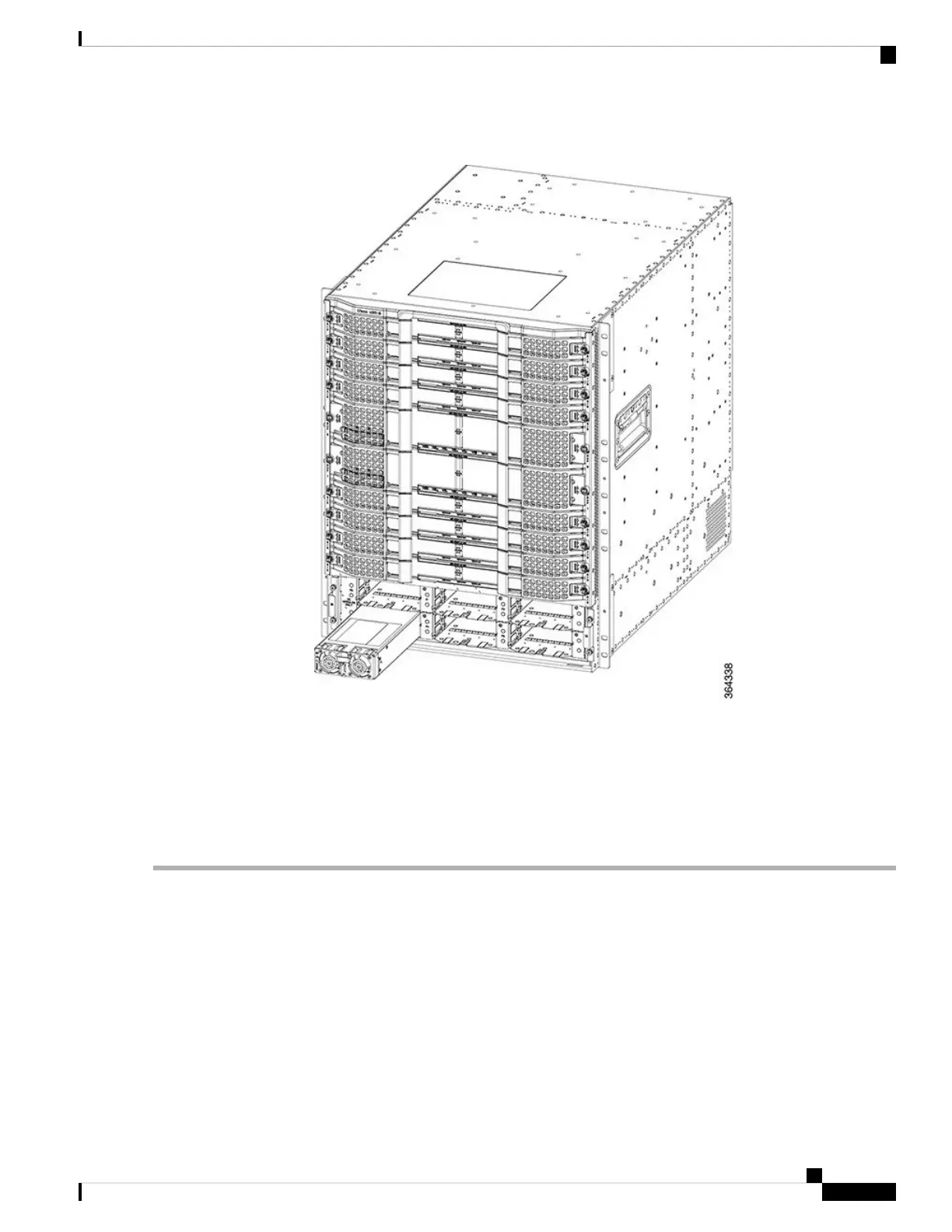
Figure 42: Installing the Power Module in the Chassis
Step 3 Move the handle up to lock the Power Module in the chassis.
Step 4 Tighten the screw using a 3/16" flat-blade screwdriver with a torque of 5-7 in-lb (0.56-0.79 Nm) to secure the Power
Module.
Step 5 Repeat Step 2, on page 82 to Step 4, on page 83 for each Power Module.
Step 6 Position the front power entry bezel on the chassis. Insert and tighten the two screws using a 3/16" flat-blade torque
screwdriver with a torque of 5-7 in-lb (0.56-0.79 Nm) to secure the bezel.
What to do next
• For an AC-powered Cisco cBR chassis, connect the AC power.
For an DC-powered Cisco cBR chassis, connect the DC power.
• If all the interfaces and other cables are connected, power up the Cisco cBR chassis.
• Verify that the input power LED on the Power Module illuminates green.
Cisco Converged Broadband Routers Hardware Installation Guide
83
Installing the Power System in the Cisco cBR Chassis
Installing the Power Module in the Cisco cBR Chassis

 Loading...


