Required Tools and Equipment
• Console cable (with mini type-B USB connector on one end, and a type-A USB connector on the other
end)
• Exar XR21V1410 UART with USB interface
• Cable with type-A USB connector on one end and DB-9 connector on the other end
• PC or terminal
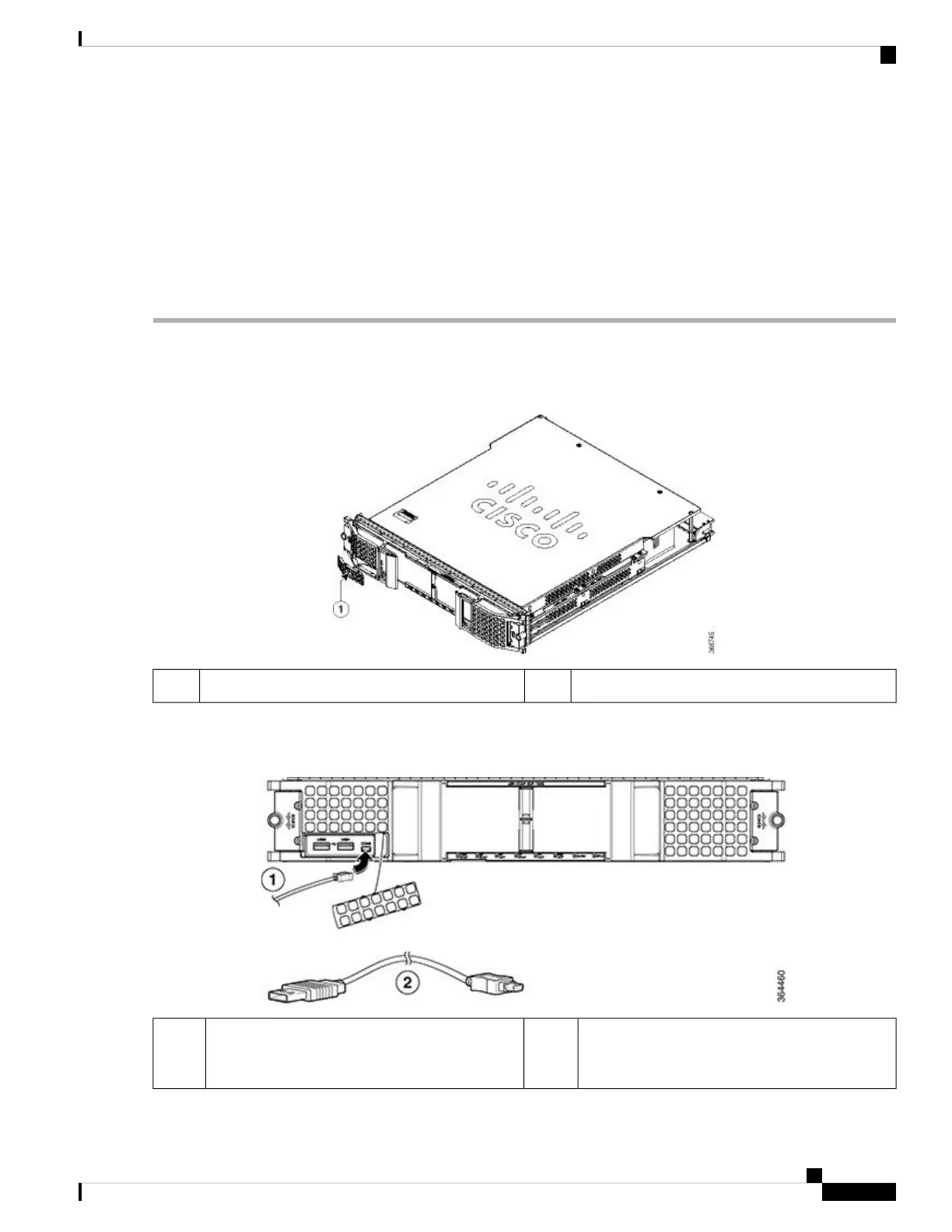
Step 1 Open the tethered I/O door on the Supervisor Card by pulling on the left edge of the door until the door is released from
the spring-loaded ejector.
Figure 96: Opening the Tethered I/O Door on the Supervisor Card
—Tethered I/O door1
Step 2 Connect the mini type-B USB connector of the console cable to the console port on the Supervisor Card.
Figure 97: Console Port Connection on the Supervisor Card
Console cable (with mini type-B USB connector
on one end, and a type-A USB connector on the
other end)
2Mini type-B USB connector1
Cisco Converged Broadband Routers Hardware Installation Guide
131
Installing the Supervisor in the Cisco cBR Chassis
Using the Console Port on the Supervisor Card

 Loading...


