Required Tools and Equipment
• ESD-preventive wrist strap
• T10 Torx-blade screwdriver
• Replacement line card or line card blank
• Antistatic Bag or mat
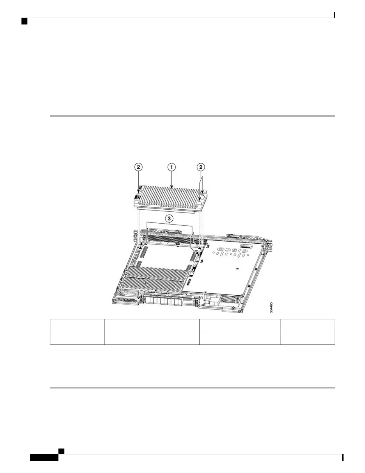
Step 1 Loosen the retaining screws (two in the front and one in the rear) using a T10 Torx-blade torque driver.
Step 2 Grasp the Downstream PHY module by its sides.
Step 3 Lift the Downstream PHY module off the cLGA connector guide pins and the rear guide pins on the line card.
Figure 151: Lift the Downstream PHY module
Guide pins3Downstream PHY module1
Captive screws2
Ensure that the Downstream PHY module is held horizontal when it is lifted off the guide pins, to prevent
damage to the cLGA connector surface.
Note
Step 4 Place the removed Downstream PHY module in an antistatic bag.
What to do next
Replace the Downstream PHY module.
Cisco Converged Broadband Routers Hardware Installation Guide
230
Maintaining the PHY Modules in the Cisco cBR Chassis
Removing the Downstream PHY Module in the Interface Line Card

 Loading...


