ValueUnit
3.7 in (9.4 cm)Height
17 lb (7.7 kg)Maximum weight
DC Power Cassette Module
16.9 in (42.92 cm)
Depth
17.3 in (43.94 cm)Width
3.7 in (9.4 cm)Height
17 lb (7.7 kg)Maximum weight
The Power Cassette Module supports six Power Modules. The front Power Module slots are numbered from
P0 to P5 on the Power Cassette Module and these designations map to the facility power outlet markings on
the rear of the chassis.
FPEM
The FPEM provides the following:
• Physical interface and interconnection to the Power Modules for either AC or DC input voltage.
• Digital communication from the Power Modules to the digital midplane.
• Power interconnection from the Power Modules to the midplane bus bar.
The FPEM is installed in the rear of the Cisco cBR chassis. It is field replaceable to allow the facility to change
from AC to DC power, or vice versa, without replacing the chassis.
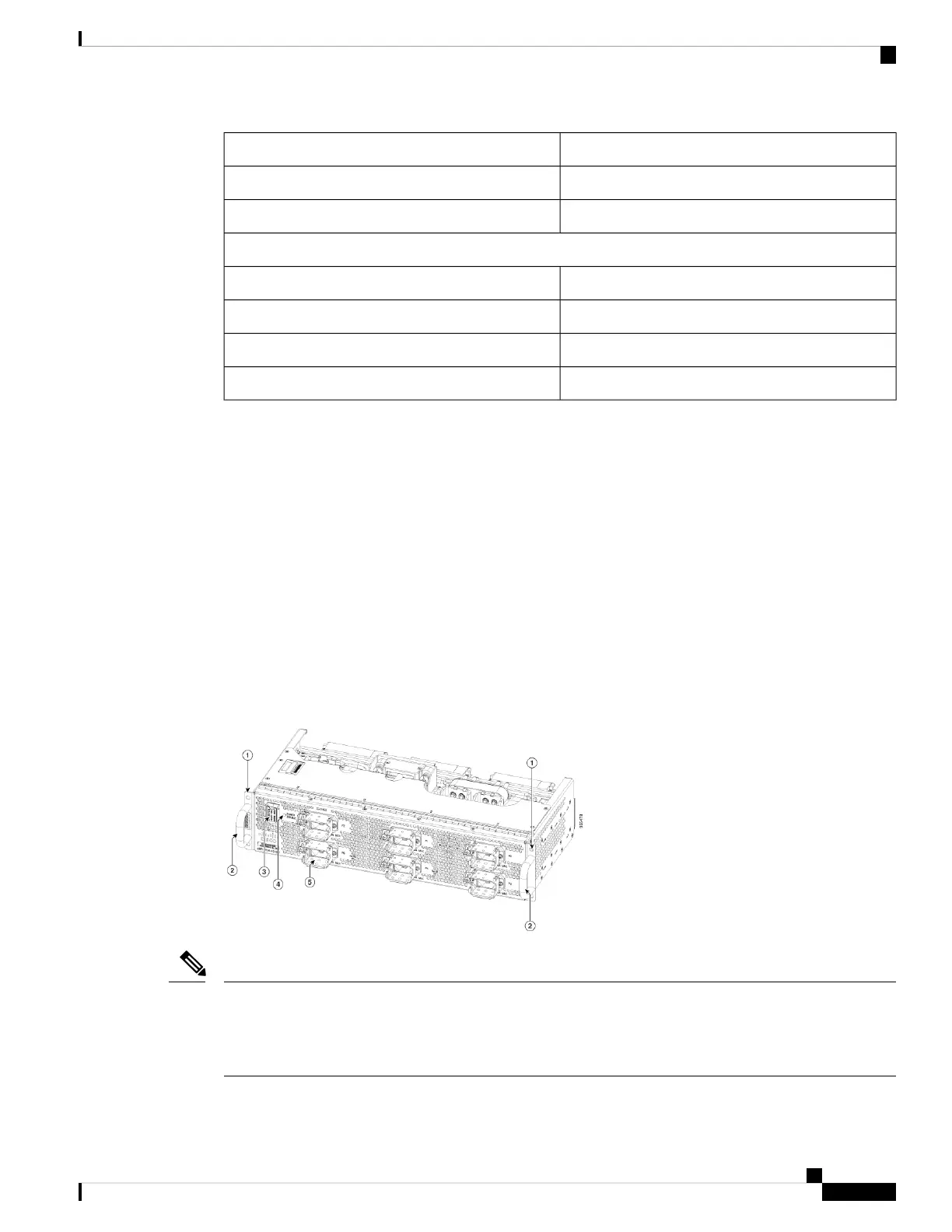
Figure 19: AC FPEM
Starting from April, 2018, Cisco ships the cBR8 router with AC FPEM VER 02 with no AC PRESENT LEDs
as shown in the figure. VER 01 of AC FPEM has P0 AC PRESENT through P5 AC PRESENT that indicates
input AC power for the corresponding AC Power Module (also indicated on the front-side of the Power
Module).
Note
Cisco Converged Broadband Routers Hardware Installation Guide
35
What is a Cisco cBR Series Converged Broadband Router
Power System

 Loading...


