connecting cables, or replacing or upgrading components). Otherwise, allow 36 inches (91.44 cm) of
access to remove field-replaceable units.
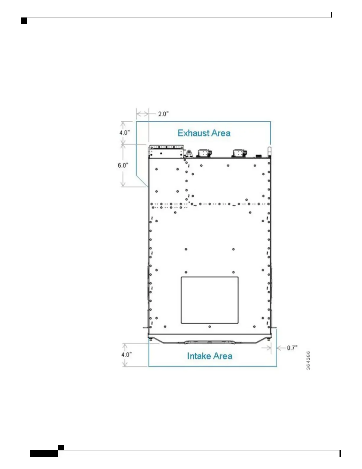
• Maintain a minimum clearance of 4 inches (10.16 cm) on the front, and rear of the chassis for the cooling
air inlet and exhaust ports, respectively. In addition, there is a small air inlet area on the front right side
of the chassis in front of the mounting ear and a small exhaust area on the rear left hand side.
Figure 24: Minimum Clearance Area
• Avoid placing the chassis in an overly congested rack or directly next to another equipment rack; otherwise,
the heated exhaust air from the other equipment can enter the inlet air vents and cause a high temperature
condition inside the router.
Cisco Converged Broadband Routers Hardware Installation Guide
52
Prepare to Install
General Rack Installation Guidelines

 Loading...


