Hydraulic System 1
23
1.7 Assembly and Installation of Hydraulic Circuit
1 Assembly of Control Valve
1. Assembling Procedure
1) Line up all the parts disassembled and check the O-ring for scratches and wears. If any defects, change it.
2) Check the spool, movement of plunger, and sheet part for any bruises. If any bruieses, smoothen them with
oilstone.
3) Clean with cleaning fluid.
4) Make sure the assembling position and direction at assembly.
5) Apply some grease to O-ring when assembling it.
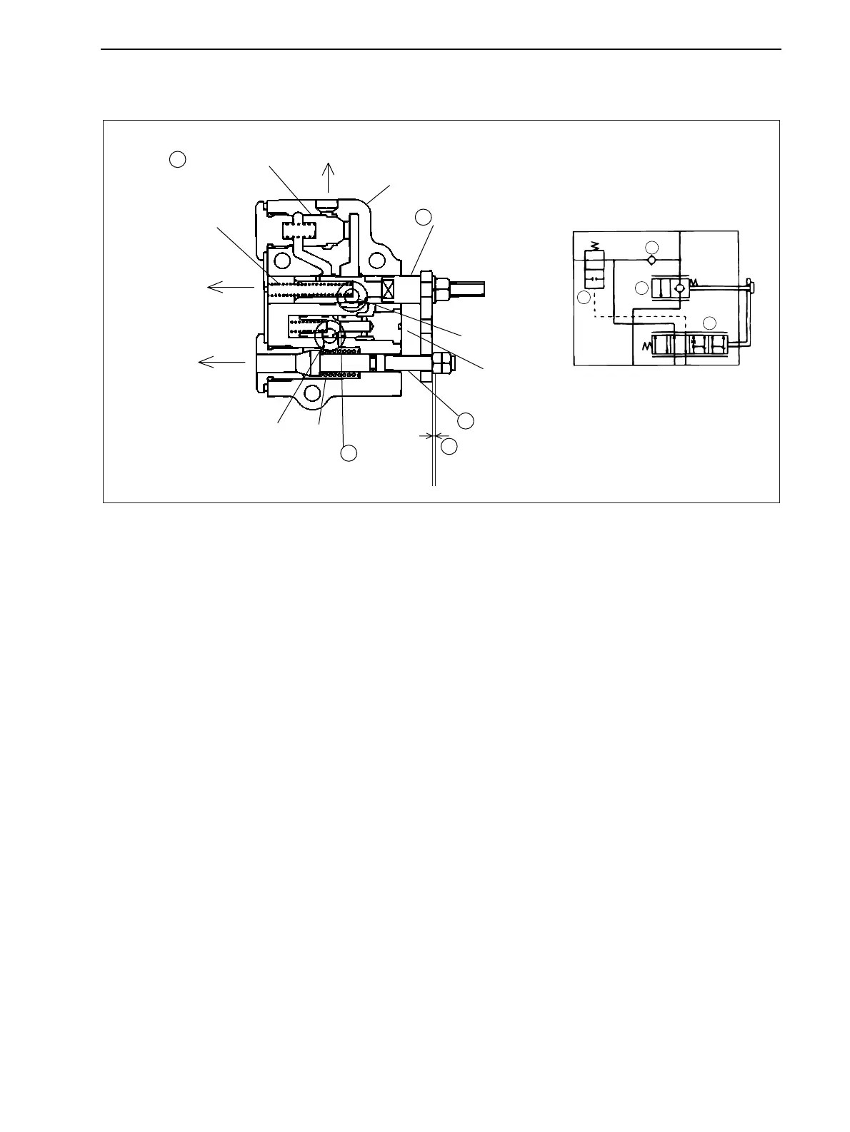
2. Adjusting Procedure
1) Remove the plug and the spring of unload valve.
2) The position, which changes the sound when moving the spool while blowing in the air from the plug, is
the neutral position for the spool.
3) Set the clearance "T" with the nut connecting the plate and poppet within 0.3 to 0.6mm {0.012 to 0.024in}
in this position and lock.
Hydraulic
pressuresignal
T
2
T1 P
C
T3
4
3
2
1
Neutraloilreturn
Valvebody
Spoolvalve
Pumpport
Poppet
Checkvalve
Poppet
spring
Cylinderport
ControlValveSectionalView
Cylinderreturn
Pilotoilreturn
Spoolvalve
spring
Unloadvalve
4
2
T0.3-0.6mm
1
3
Sheet
GZ3W31-024A
www.mymowerparts.com
K&T Saw Shop 606-678-9623 or 606-561-4983
 Loading...