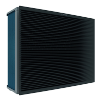
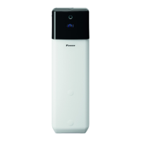
Refrigerant Circuit ESIE09-08B
8 Refrigerant Circuit
1. Refrigerant Circuit
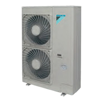
1.1 Outdoor Unit
ERRQ - ERSQ
No. in
refrigerant
system
diagram
Symbol Name Major Function
A M1C Inverter compressor (INV)
Inverter compressor is operated on frequencies between 36 Hz and 195 Hz by using
the invert
er. In total there are 31 steps.
B
M1F
M2F
Inverter fan
Since the system is of air heat exchanging type
, the fan is o
perated at 8 (9)-step
rotation speed by using the inverter.
C Y1E
Electronic expansion valve
(Main: EV1)
While in heating operation, PI control is applied to keep
the outlet superheated degree
of air heat exchanger constant.
D Y3E
Electronic expansion valve
(Subcool: EV3)
Pl control is applied to keep the outlet superheated degree of subcooling he
at
e
xchanger constant.
E Y2S Solenoid valve (Hot gas: SVP) Used to prevent the low pressure from transient fallin
g.
F Y3S
Solenoid valve (Unload circuit
SVU
L)
Used to the unloading operation of compressor.
G Y1S Four way valve
Used to switch the operation mode between defrosting and heating. Activated during
h
eating
(opposite concerning indoor unit).
H S1NPH High pressure sensor Used to detect high pressure.
I S1NPL Low pressure sensor Used to detect low pressure.
J S1PH
HP pressure switch (For INV
com
p
ressor)
In order to prevent the increase of high pr
essure when a malfunction occurs, this
switch is activated at high pressure of 4.0 MPa or more to stop the compressor
operation.
K —
Pressure regulating valve 1
(Receiver to discharge pipe
)
This valve opens at a pressure of 4.0 MPa for prevention o
f pressure increase, thus
resulting in no damage of functional parts due to the increase of pressure in
transportation or storage.
1 R1T Thermistor (Outdoor air: Ta) Used to detect outdoor temperature, correct
disch
arge pipe temperature, and others.
2 R2T
Thermistor (INV discharge
pipe: Tdi)
used to detect discharge pipe temperature, make th
e temperature
protection control of
compressor, and others.
3 R3T
Thermistor
(Suction pipe1: Ts1)
used to detect suction pipe temperature, keep the suction su
perheated degree
constant in heating operation, and others.
4 R4T
Thermistor (Heat exchanger
deicer:
Tb)
U
sed to detect liquid pipe temperature of air heat exchanger, determine defrosting
operation, and others.
5 R5T
Thermistor
(Suction pipe2: Ts2)
Used to the calculation of superheat and internal temperature of compressor etc.
6 R6
T
Thermistor (Subcooling heat
exchanger gas pipe
: Tsh)
U
sed to control of subcooling electronic expansion valve.
7 R7
T
Thermistor
(Liquid pipe1: Tl1)
Liquid thermistor (internal control), and others.
8 R8T
Thermistor
(Liquid pipe2: Tl2)
Liquid thermistor (internal control), and others.
 Loading...
