Refrigerant Circuit ESIE09-08B
10 Refrigerant Circuit
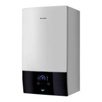
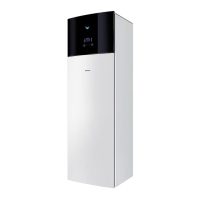
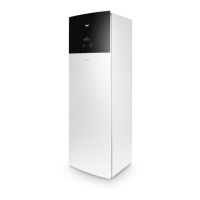
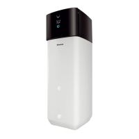
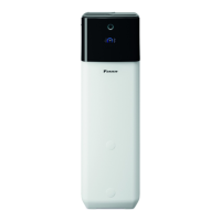
1.2 Indoor Unit
EKHBRD 011/014/016 AA/AB(V1/Y1)
No. in
refrigerant
system
diagram
Symbol Name Major Function
A M1C
Inverter compressor on
R-134a
Inverter compressor is operated on frequencies between 40 Hz and 210 Hz by using
the invert
er. Max. of 30 steps.
B Y1R Four way valve
Used to switch the operation mode between heating and defrost. Not activat
ed during
heating (opposite concerning outdoor unit).
C B1PL Low pressure sensor Used to detect low pressure.
D B1PH High pressure sensor Used to detect high pressure.
E S1PH High pressure switch
In order to prevent the increase of high pr
essure when a malfunction occurs, this
switch is activated at high pressure of 3.8 MPa or more to stop the compressor
operation.
F K2S 2-way valve Used during defrost operation.
G K1E Electronic expansion valve Used to regulate the refrigerant flow of R-410A.
H K2E Electronic expansion valve Used to regulate the refrigerant flow of R-134a.
I E1HC Crankcase heater
Used to prevent migration (when the unit is OFF)
and condensation of refrigerant in
the crankcase of compressor.
J M1P DC inverter pump Used to regulate water flow to achieve a constant ∆T.
K Q2L
Thermistor protector water
piping
Used to protect the water system against high temperatures.
L K1S
3 way valve (option for water
tank)
Used to switch over between space heating and domestic ho
t water.
1 R3T Liquid thermistor R-410A Subcool calculation.
2 R6T Discharge thermistor
Used to detect discharge pipe temperature, make
the tem
perature protection control of
compressor, and others.
3 R7T Liquid thermistor R-134a Subcool calculation.
4 R4T Returning water thermistor Used to control and protect the water system.
5 R5T Leaving water thermistor Used to control and protect the water system.
 Loading...
