12.2 Parallel Drive System Disassembly and Assembly
12.2.1 Removing the Control Shelf
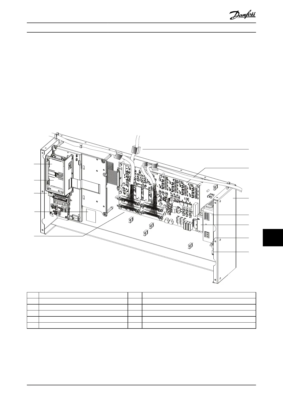
To remove the control shelf assembly, use the following steps. See Illustration 12.2.
1. Disconnect the relay cable from the corresponding relay connector on the top of the drive module.
2. Disconnect the 44-pin ribbon cables from the MDCIC plug on the top of the drive module.
3. If the drive module has an external LCP, disconnect the LCP cable from the connector on the control shelf.
4. Unfasten the mounting bracket and remove the control shelf assembly.
5. Place the control shelf assembly in an ESD-protected package.
1 LCP cradle 7 Multi-drive control interface card (MDCIC)
2 Control card (underneath LCP cradle) 8 Control shelf
3 Control terminal blocks 9 Switched mode power supply (SMPS)
4 Product label 10 Pilz relay
5 44-pin cables from MDCIC to drive modules 11 DIN rail
6 Ferrite core 12 Terminal block mounted on DIN rail
Illustration 12.2 Control Shelf Disassembly for a 4-module System
Da2/Db2/Da4/Db4 Parallel Sy... Service Guide
MG94A502 Danfoss A/S © 02/2019 All rights reserved. 249
12 12
 Loading...


